Arduino UNO Based Temperature Monitoring System with GSM Notification and Relay-Controlled Fan
Circuit Documentation
Summary of the Circuit
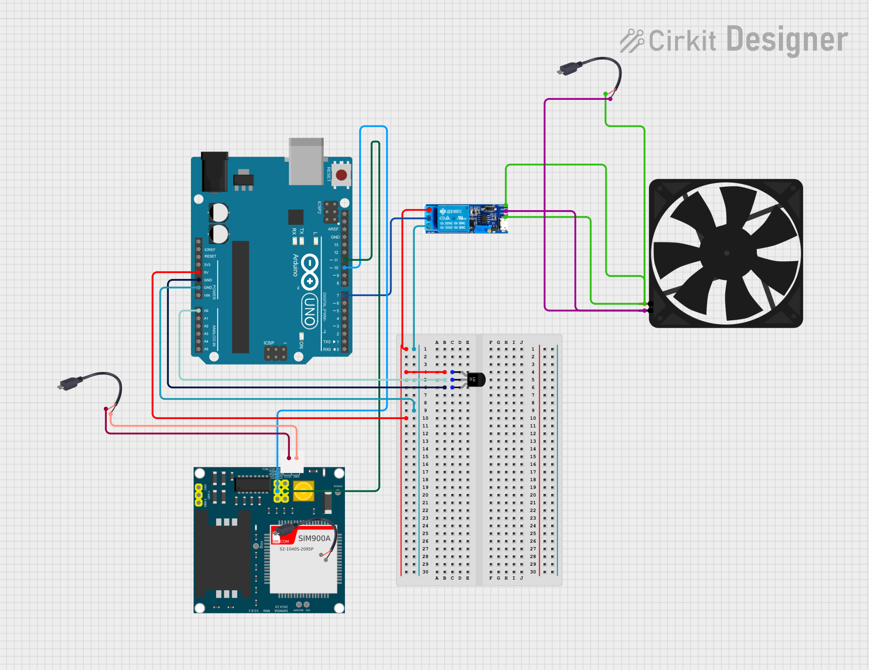
This circuit integrates an Arduino UNO microcontroller with a SIM900A GSM module, a relay module, a temperature sensor (LM35), a fan, and power supply modules via micro USB to cable connectors. The Arduino UNO is used as the central processing unit to control the relay based on the temperature readings from the LM35 sensor and to communicate with the SIM900A GSM module. The relay controls the power to the fan, turning it on or off based on the temperature. The SIM900A module allows for GSM network communication, enabling potential features like remote monitoring or control via SMS or voice. The micro USB to cable connectors are used to provide power to the circuit components.
Component List
Arduino UNO
- Microcontroller board based on the ATmega328P
- Provides digital and analog I/O pins
- Can be programmed via USB connection
SIM900A
- GSM/GPRS module
- Capable of sending SMS, making voice calls, and connecting to the internet
- Interfaces with the Arduino via serial communication
Relay Module 5V-30V
- Electromechanical switch that can be controlled by the Arduino
- Used to turn the fan on and off
- Has normally open (NO), normally closed (NC), and common contact (COM) terminals
Temperature Sensor (LM35)
- Precision integrated-circuit temperature sensor
- Outputs an analog voltage proportional to the temperature
- Easy to interface with the Arduino analog input
Micro USB to Cable (2 Pin)
- Power supply connector
- Provides 5V power from a USB port to the circuit
Fan
- 5V DC fan
- Used for cooling based on the temperature sensor reading
Wiring Details
Arduino UNO
5Vconnected to the relay module (normally open) and temperature sensor (LM35)+VsGNDconnected to the relay module (normally closed) and temperature sensor (LM35)GNDA0connected to the temperature sensor (LM35)VoutD11connected to the SIM900A5VRD10connected to the SIM900A5VTD7connected to the relay modulecommon contact
SIM900A
GNDconnected to the micro USB to cable connector-5Vconnected to the micro USB to cable connector+5VRconnected to Arduino UNOD115VTconnected to Arduino UNOD10
Relay Module 5V-30V
normally openconnected to the temperature sensor (LM35)+Vsand Arduino UNO5Vnormally closedconnected to Arduino UNOGNDcommon contactconnected to Arduino UNOD7triggerconnected to the fan5Vand micro USB to cable connector+V+connected to the fan5Vand micro USB to cable connector+V-connected to the fanGNDand micro USB to cable connector-
Temperature Sensor (LM35)
+Vsconnected to the relay module (normally open) and Arduino UNO5VVoutconnected to Arduino UNOA0GNDconnected to Arduino UNOGND
Micro USB to Cable (2 Pin)
+connected to the SIM900A5V, relay moduleV+, and fan5V-connected to the SIM900AGND, relay moduleV-, and fanGND
Fan
5Vconnected to the relay moduletriggerandV+GNDconnected to the relay moduleV-
Documented Code
Arduino UNO Code (sketch.ino)
void setup() {
  // put your setup code here, to run once:

}

void loop() {
  // put your main code here, to run repeatedly:

}
Note: The provided code is a template and does not contain any functional code. It needs to be populated with the logic for reading the temperature sensor, controlling the relay, and interfacing with the SIM900A module.