Cirkit Designer
Your all-in-one circuit design IDE
Home /
Project Documentation
ESP32-Based Access Control System with RFID and Keypad Input

Circuit Documentation
Summary
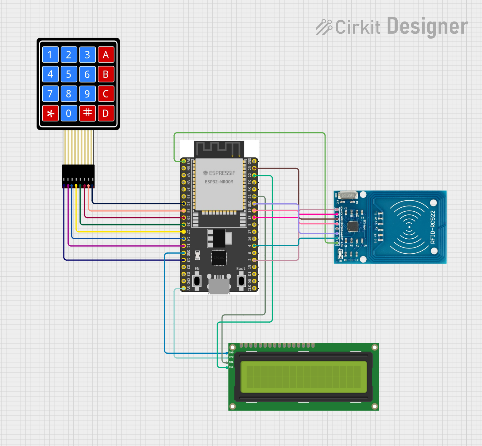
This document provides a detailed overview of a circuit that integrates an RFID-RC522 module, a 4x4 Membrane Matrix Keypad, an ESP32 Wroom Dev Kit microcontroller, and an I2C LCD 16x2 Screen. The ESP32 microcontroller serves as the central processing unit, interfacing with the RFID module for tag reading, the keypad for user input, and the LCD screen for displaying information. The circuit is designed for applications that require user interaction and data display, such as access control systems.
Component List
RFID-RC522
- Description: An RFID reader/writer module for contactless communication at 13.56MHz.
- Pins: VCC (3.3V), RST, GND, IRQ, MISO, MOSI, SCK, SDA
4X4 Membrane Matrix Keypad
- Description: A 16-button keypad for user input.
- Pins: R1, R2, R3, R4, C1, C2, C3, C4
ESP 32 Wroom Dev Kit
- Description: A powerful microcontroller with Wi-Fi and Bluetooth capabilities.
- Pins: 3V3, EN, VP, VN, GPIO 34, GPIO 35, GPIO 32, GPIO 33, GPIO 25, GPIO 26, GPIO 27, GPIO 14, GND, GPIO 13, SD2, SD3, CMD, V5, GPIO 23, GPIO 22, TXD, RXD, GPIO 21, GPIO 19, GPIO 18, GPIO 5, GPIO 17, GPIO 16, GPIO 4, GPIO 0, GPIO 2, GPIO 15, SD1, SD0, CLK
I2C LCD 16x2 Screen
- Description: A liquid crystal display capable of displaying 16 characters per 2 lines.
- Pins: SCL, SDA, VCC (5V), GND, VDD, VO, RS, RW, E, D0, D1, D2, D3, D4, D5, D6, D7, BLA, BLK
Wiring Details
RFID-RC522
- VCC (3.3V) connected to ESP 32 Wroom Dev Kit 3V3
- RST connected to ESP 32 Wroom Dev Kit GPIO 4
- GND connected to ESP 32 Wroom Dev Kit GND
- MISO connected to ESP 32 Wroom Dev Kit GPIO 19
- MOSI connected to ESP 32 Wroom Dev Kit GPIO 23
- SCK connected to ESP 32 Wroom Dev Kit GPIO 18
- SDA connected to ESP 32 Wroom Dev Kit GPIO 2
4X4 Membrane Matrix Keypad
- R1 connected to ESP 32 Wroom Dev Kit GPIO 13
- R2 connected to ESP 32 Wroom Dev Kit GPIO 14 (Note: R2 and R3 share the same GPIO, which may be an error)
- R3 connected to ESP 32 Wroom Dev Kit GPIO 14
- R4 connected to ESP 32 Wroom Dev Kit GPIO 27
- C1 connected to ESP 32 Wroom Dev Kit GPIO 26
- C2 connected to ESP 32 Wroom Dev Kit GPIO 25
- C3 connected to ESP 32 Wroom Dev Kit GPIO 33
- C4 connected to ESP 32 Wroom Dev Kit GPIO 32
I2C LCD 16x2 Screen
- SCL connected to ESP 32 Wroom Dev Kit GPIO 22
- SDA connected to ESP 32 Wroom Dev Kit GPIO 21
- VCC (5V) connected to ESP 32 Wroom Dev Kit V5
- GND connected to ESP 32 Wroom Dev Kit GND
Documented Code
sketch.ino
void setup() {
  // put your setup code here, to run once:

}

void loop() {
  // put your main code here, to run repeatedly:

}
documentation.txt
(No additional documentation provided)
Please note that the provided code is a template and does not include any functionality. Additional code is required to initialize the components, handle the communication between them, and implement the desired features of the circuit.