
Arduino UNO Based Air Quality and Fire Detection System with RGB Indicator and Alarm
View and Edit Project In Cirkit Designer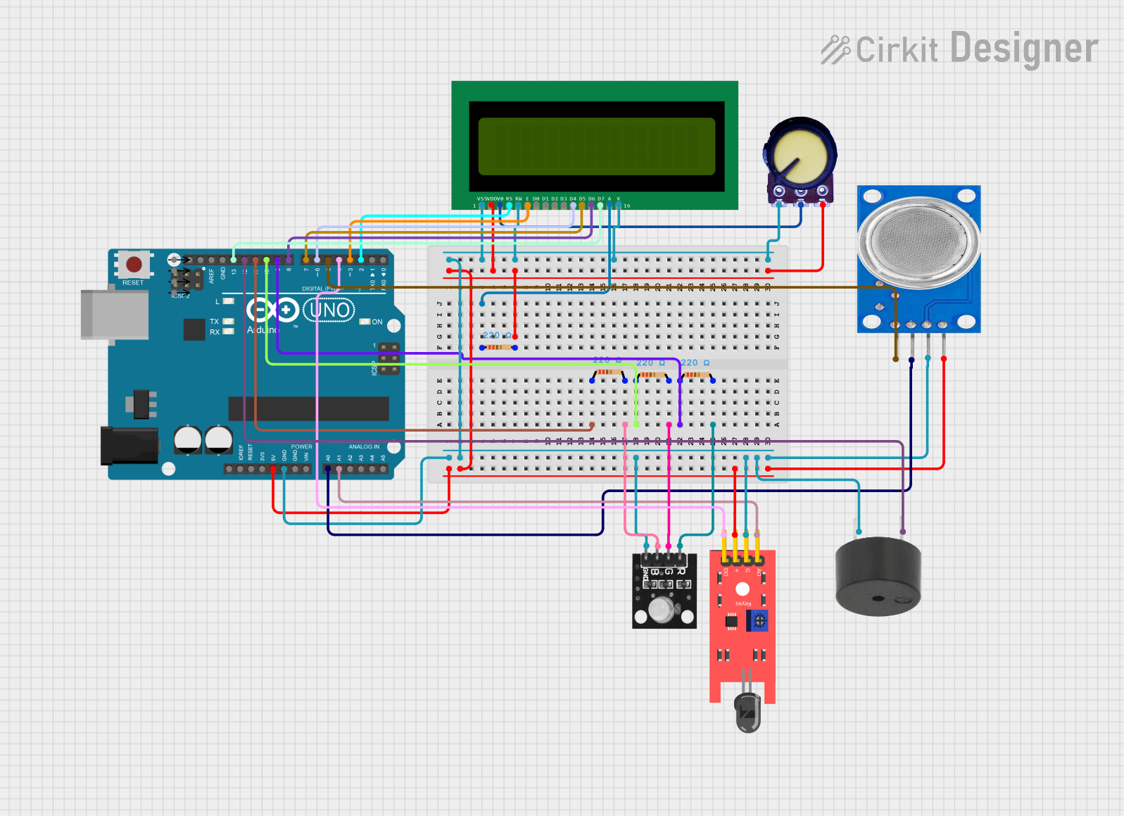
Circuit Documentation
Summary
This circuit is designed to monitor environmental parameters such as CO2 levels and the presence of flames, and to provide visual feedback through an LCD display and an RGB LED. It includes sensors for detecting CO2 (MQ135) and flames (KY-026 Flame Sensor), a buzzer for audible alerts, and a 16x2 LCD for displaying status messages. The Arduino UNO serves as the central microcontroller, interfacing with the various components to process sensor data and control outputs.
Component List
Arduino UNO
- Microcontroller board based on the ATmega328P
- Used as the main controller for the circuit
Qwiic Cable - Breadboard Jumper (4-pin)
- Used for easy connection between components with a Qwiic connector
MQ135
- Air quality sensor for detecting hazardous gases including CO2
- Provides both analog and digital outputs
16X2 LCD
- Alphanumeric liquid crystal display
- Displays information such as CO2 levels and flame detection status
Potentiometer
- Variable resistor, typically used for adjusting LCD contrast
Resistor (220 Ohms)
- Four resistors used for current limiting in various parts of the circuit
Buzzer
- Emits an audible alert when certain conditions are met (e.g., high CO2 levels or flame detection)
KY-026 Flame Sensor
- Detects flames or fire through infrared light
- Provides both analog and digital outputs
RGB Led module
- Multicolor LED capable of displaying various colors
- Used to provide visual feedback based on sensor readings
Wiring Details
Arduino UNO
- 5V and GND pins provide power to the sensors, LCD, and other components
- Digital pins D4-D13 are used to interface with the LCD, buzzer, and sensors
- Analog pins A0 and A1 are used to read values from the MQ135 and KY-026 sensors
MQ135
- VCC connected to 5V power supply
- GND connected to ground
- A0 connected to Arduino's A0 pin for analog gas concentration reading
- D0 (unused in this circuit)
16X2 LCD
- VDD connected to 5V power supply
- VSS, RW, and K connected to ground
- V0 connected to the wiper of the potentiometer for contrast adjustment
- RS, E, D4-D7 connected to Arduino's digital pins D2, D3, D6-D9 for data/command transmission
Potentiometer
- One side connected to 5V power supply
- Wiper connected to LCD's V0 pin for contrast adjustment
- Other side connected to ground
Resistor (220 Ohms)
- Four resistors used to limit current to the buzzer and RGB LED module
- One resistor connected between Arduino's D11 and RGB LED's blue channel
- One resistor connected between Arduino's D10 and RGB LED's green channel
- One resistor connected between Arduino's D9 and RGB LED's red channel
- One resistor connected between Arduino's 5V and LCD's A pin for backlight
Buzzer
- PIN connected to Arduino's D12 through a 220 Ohm resistor
- GND connected to ground
KY-026 Flame Sensor
- VCC connected to 5V power supply
- GND connected to ground
- A0 (unused in this circuit)
- D0 connected to Arduino's D4 for digital flame detection
RGB Led module
- Red channel connected to Arduino's D9 through a 220 Ohm resistor
- Green channel connected to Arduino's D10 through a 220 Ohm resistor
- Blue channel connected to Arduino's D11 through a 220 Ohm resistor
- GND connected to ground
Documented Code
#include <LiquidCrystal.h>

// Initialize the library with the numbers of the interface pins
LiquidCrystal lcd(2, 3, 6, 7, 8, 13); // LCD Pins: RS, E, D4, D5, D6, D7

const int CO2_PIN = A0;
const int FLAME_ANALOG_PIN = A1;
const int FLAME_DIGITAL_PIN = 4; // Updated Digital Pin for KY-026
const int BUZZER_PIN = 12;       // Updated Digital Pin for Buzzer
const int RED_PIN = 9;           // Updated Red Pin for RGB LED
const int GREEN_PIN = 10;        // Updated Green Pin for RGB LED
const int BLUE_PIN = 11;         // Updated Blue Pin for RGB LED
const int SAFE_CO2_LEVEL = 1000; // Example threshold value
const int RGB_SCALE = 4;         // Scaling factor for RGB

void setup() {
  lcd.begin(16, 2);
  pinMode(BUZZER_PIN, OUTPUT);
  pinMode(FLAME_DIGITAL_PIN, INPUT);
  pinMode(RED_PIN, OUTPUT);
  pinMode(GREEN_PIN, OUTPUT);
  pinMode(BLUE_PIN, OUTPUT);

  lcd.print("Setup Complete");
  delay(2000);
  lcd.clear();
}

void loop() {
  int co2Value = analogRead(CO2_PIN);
  int flameDigitalValue = digitalRead(FLAME_DIGITAL_PIN);

  // Clear LCD before updating
  lcd.clear();

  // Display CO2 levels
  lcd.setCursor(0, 0);
  lcd.print("CO2: ");
  lcd.print(co2Value);
  lcd.print(" PPM");

  // Check CO2 levels and activate buzzer if necessary
  if (co2Value > SAFE_CO2_LEVEL) {
    digitalWrite(BUZZER_PIN, HIGH);
  } else {
    digitalWrite(BUZZER_PIN, LOW);
  }

  // Check for fire and display warning
  lcd.setCursor(0, 1);
  if (flameDigitalValue == LOW) { // Assuming LOW indicates flame detected
    lcd.print("Fire Detected! ");
    digitalWrite(BUZZER_PIN, HIGH); // Sound buzzer if fire is detected
  } else {
    lcd.print("No Fire       ");
  }

  // Control RGB LED based on CO2 levels
  analogWrite(RED_PIN, co2Value / RGB_SCALE);       // Scale to 0-255
  analogWrite(GREEN_PIN, 255 - (co2Value / RGB_SCALE));
  analogWrite(BLUE_PIN, (co2Value / RGB_SCALE) / 2);

  delay(1000); // Update every second
}
This code is designed to run on the Arduino UNO and controls the LCD, buzzer, and RGB LED based on readings from the MQ135 CO2 sensor and the KY-026 Flame Sensor. It provides visual and audible alerts when CO2 levels exceed a predefined threshold or when flames are detected.