Solar-Powered Climate Control System with Arduino and ESP8266
Circuit Documentation
Summary
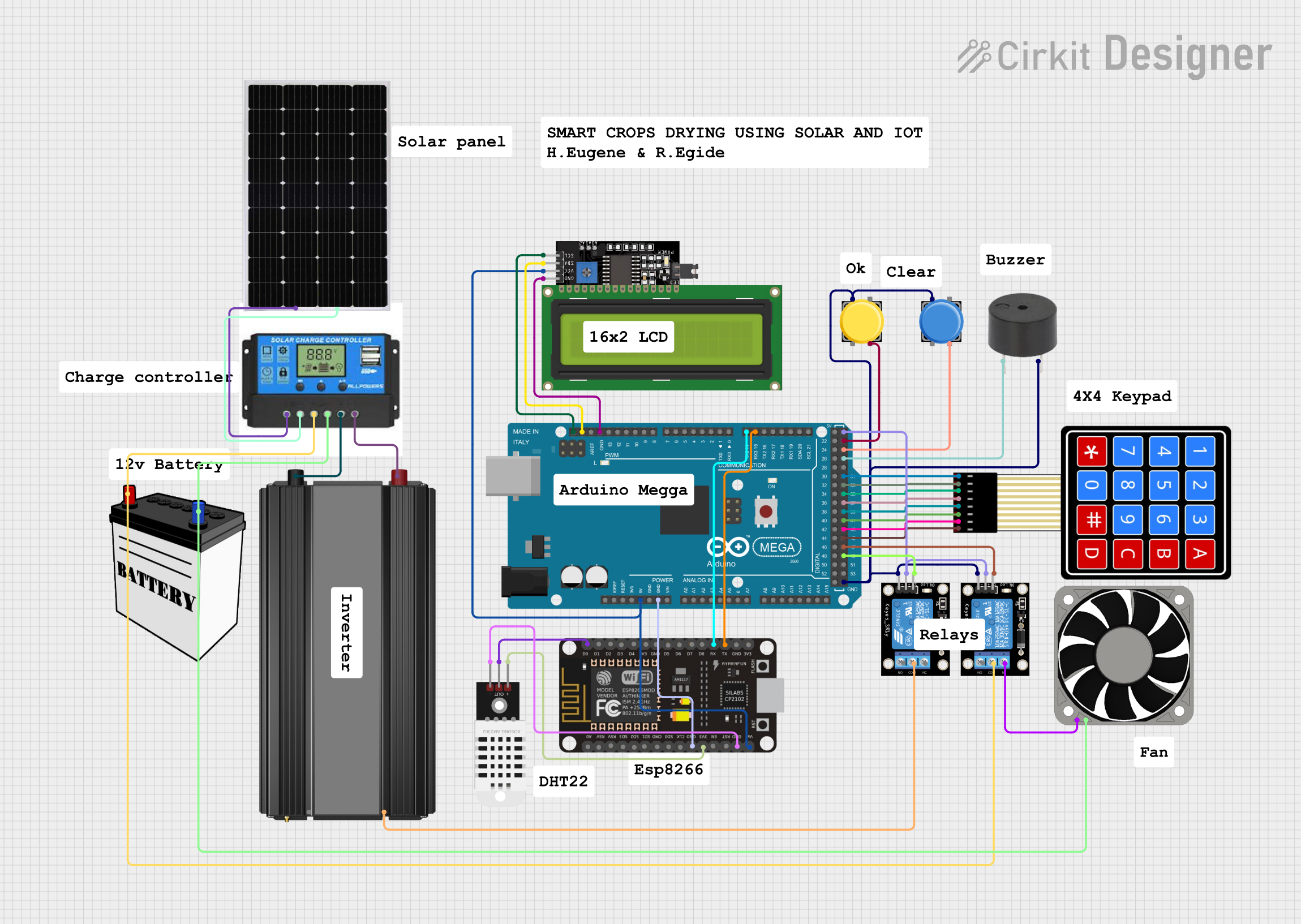
This circuit is designed to interface various components including an Arduino Mega 2560, an ESP8266 NodeMCU, relay modules, a charge controller, a 12V battery, a solar panel, a power inverter, a buzzer, an LCD display, a 4x4 membrane matrix keypad, pushbuttons, and a DHT22 sensor. The Arduino Mega 2560 serves as the central processing unit, controlling relays, reading user inputs from the keypad and pushbuttons, and communicating with the ESP8266 NodeMCU for potential IoT capabilities. The ESP8266 NodeMCU is also interfaced with a DHT22 sensor for environmental data. The circuit is powered by a solar panel charging a 12V battery through a charge controller, which also manages the power distribution to the load and the power inverter.
Component List
- Arduino Mega 2560: A microcontroller board based on the ATmega2560, with numerous digital and analog I/O pins.
- ESP8266 NodeMCU: A Wi-Fi enabled microcontroller module with GPIO pins.
- KY-019 Relay Module 1 Channel: A relay module that allows for the control of high power devices.
- Charge Controller: Manages the charging of the 12V battery from the solar panel and provides power to the load.
- 12V Battery: Stores electrical energy for use by the circuit.
- Solar Panel: Converts solar energy into electrical energy to charge the battery.
- Power Inverter: Converts DC power from the battery to AC power for AC loads.
- LCD Display 16x4 I2C: An alphanumeric liquid crystal display with an I2C interface.
- 4X4 Membrane Matrix Keypad: A keypad with 16 buttons arranged in a 4x4 matrix.
- Pushbutton: A simple switch mechanism for controlling some aspect of a machine or a process.
- Buzzer: An audio signaling device.
- 40 Fan 12v: A 12V fan for cooling purposes.
- DHT22: A sensor for measuring temperature and humidity.
Wiring Details
Arduino Mega 2560
5Vconnected to ESP8266 NodeMCUVIN, LCD DisplayVCC, and both KY-019 Relay Modules5V.GNDconnected to ESP8266 NodeMCUGND, LCD DisplayGND, buzzerGND, both KY-019 Relay ModulesGND, and both pushbuttonsPin 1.D15/RX3connected to ESP8266 NodeMCUTX.D14/TX3connected to ESP8266 NodeMCURX.SDAconnected to LCD DisplaySDA.SCLconnected to LCD DisplaySCL.D49connected to KY-019 Relay ModuleS.D47connected to KY-019 Relay ModuleS.D45,D43,D41,D39,D37,D35,D33,D31connected to correspondingC4,C3,C2,C1,R4,R3,R2,R1pins of the 4X4 Membrane Matrix Keypad.D27connected to buzzerPIN.D25connected to pushbuttonPin 4.D23connected to pushbuttonPin 4.
ESP8266 NodeMCU
VINconnected to Arduino Mega 25605V.GNDconnected to Arduino Mega 2560GND.TXconnected to Arduino Mega 2560D15/RX3.RXconnected to Arduino Mega 2560D14/TX3.D0connected to DHT22Out.3V3connected to DHT22+.GNDconnected to DHT22-.
KY-019 Relay Module 1 Channel (x2)
5Vconnected to Arduino Mega 25605V.GNDconnected to Arduino Mega 2560GND.Sconnected to Arduino Mega 2560D49orD47.NCof one relay connected to 40 Fan 12v+12V.COMof one relay connected to Charge ControllerBattery Positiveand 12V BatteryVCC.COMof the other relay connected to Power Inverter+.
Charge Controller
Solar Positiveconnected to Solar Panel+.Solar Negativeconnected to Solar Panel-.Battery Positiveconnected to KY-019 Relay ModuleCOMand 12V BatteryVCC.Battery Negativeconnected to 40 Fan 12v-12Vand 12V BatteryGND.Load Positiveconnected to Power Inverter-.Load Negativeconnected to Power Inverter+.
12V Battery
VCCconnected to Charge ControllerBattery Positiveand KY-019 Relay ModuleCOM.GNDconnected to Charge ControllerBattery Negative.
Solar Panel
+connected to Charge ControllerSolar Positive.-connected to Charge ControllerSolar Negative.
Power Inverter
-connected to Charge ControllerLoad Positive.+connected to Charge ControllerLoad Negativeand KY-019 Relay ModuleCOM.
LCD Display 16x4 I2C
SDAconnected to Arduino Mega 2560SDA.SCLconnected to Arduino Mega 2560SCL.VCCconnected to Arduino Mega 25605V.GNDconnected to Arduino Mega 2560GND.
4X4 Membrane Matrix Keypad
C4,C3,C2,C1,R4,R3,R2,R1connected to corresponding Arduino Mega 2560D45,D43,D41,D39,D37,D35,D33,D31.
Pushbutton (x2)
Pin 4connected to Arduino Mega 2560D25orD23.Pin 1connected to Arduino Mega 2560GND.
Buzzer
PINconnected to Arduino Mega 2560D27.GNDconnected to Arduino Mega 2560GND.
DHT22
Outconnected to ESP8266 NodeMCUD0.+connected to ESP8266 NodeMCU3V3.-connected to ESP8266 NodeMCUGND.
Documented Code
Arduino Mega 2560 Code (sketch.ino)
void setup() {
  // put your setup code here, to run once:

}

void loop() {
  // put your main code here, to run repeatedly:

}
ESP8266 NodeMCU Code
No code provided for the ESP8266 NodeMCU.
This documentation provides an overview of the circuit, including the components used, their wiring connections, and the code for the Arduino Mega 2560. The ESP8266 NodeMCU code is not included in the provided inputs.