
DIP Switch Controlled LED Indicator Circuit with AND Gate Logic
View and Edit Project In Cirkit Designer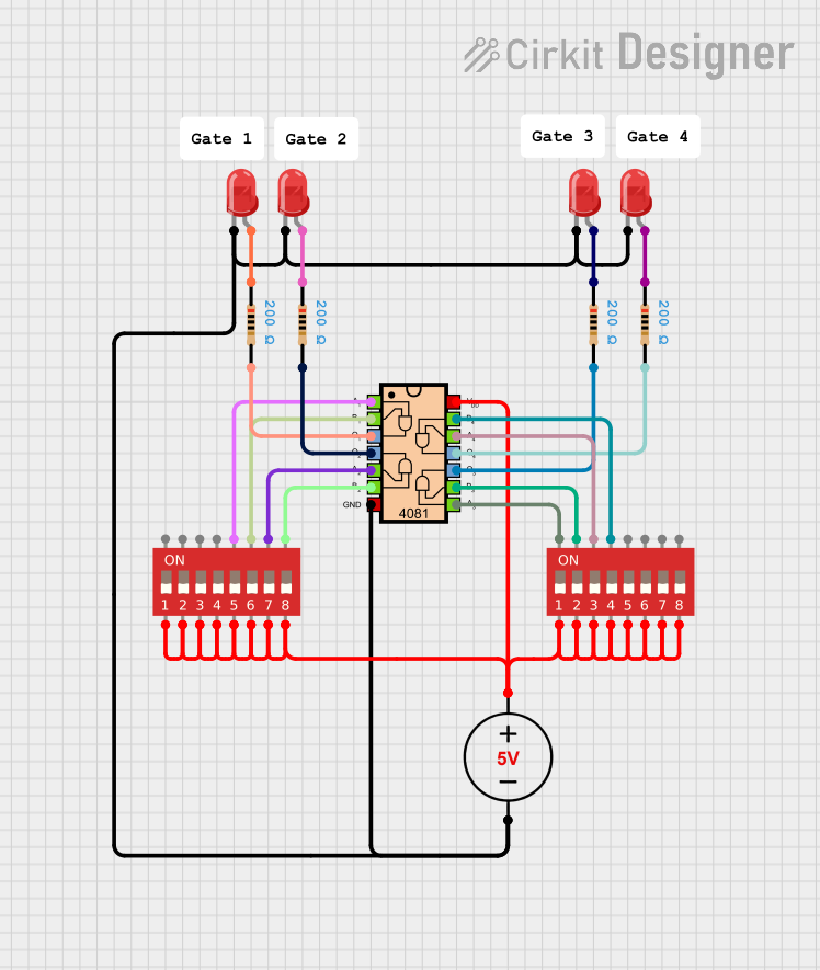
Circuit Documentation
Summary
This circuit is designed to utilize a 5V DC power supply to power multiple LED indicators and a CD4081 Quad Input AND Gate IC. The circuit incorporates DIP switches to control the inputs to the AND gate, allowing for various configurations based on the switch positions. Resistors are used to limit the current flowing through the LEDs, ensuring safe operation.
Component List
5V DC Power Supply
- Description: Provides a stable 5V power source for the circuit.
- Pins: Positive, Negative
LED Two Pin (Red)
- Description: Emits red light when powered. Used as indicators in the circuit.
- Pins: Cathode, Anode
DIP Switch (8 Position)
- Description: An 8-position switch that allows for binary input selection. Each switch can be toggled on or off.
- Pins: 1b, 2b, 3b, 4b, 5b, 6b, 7b, 8b, 1a, 2a, 3a, 4a, 5a, 6a, 7a, 8a
Resistor
- Description: Limits the current flowing through the LEDs to prevent damage.
- Pins: pin1, pin2
- Properties: Resistance: 200 Ohms
CD4081 Quad Input AND Gate IC
- Description: A digital logic gate that outputs true only when all its inputs are true.
- Pins: VDD, GND, A1, A2, A3, A4, B1, B2, B3, B4, Q1, Q2, Q3, Q4
Wiring Details
5V DC Power Supply
Positive connects to:
- DIP Switch (8 Position) - 3a
- DIP Switch (8 Position) - 4a
- DIP Switch (8 Position) - 5a
- DIP Switch (8 Position) - 6a
- DIP Switch (8 Position) - 7a
- DIP Switch (8 Position) - 8a
- DIP Switch (8 Position) - 1a
- DIP Switch (8 Position) - 2a
- CD4081 Quad Input AND Gate IC - VDD
Negative connects to:
- LED Two Pin (Red) - Cathode (1)
- LED Two Pin (Red) - Cathode (2)
- LED Two Pin (Red) - Cathode (3)
- LED Two Pin (Red) - Cathode (4)
- CD4081 Quad Input AND Gate IC - GND
LED Two Pin (Red) (1)
- Anode connects to:
- Resistor - pin1
LED Two Pin (Red) (2)
- Anode connects to:
- Resistor - pin1
LED Two Pin (Red) (3)
- Anode connects to:
- Resistor - pin1
LED Two Pin (Red) (4)
- Anode connects to:
- Resistor - pin1
DIP Switch (8 Position) (1)
- 1b connects to:
- CD4081 Quad Input AND Gate IC - A3
DIP Switch (8 Position) (2)
- 2b connects to:
- CD4081 Quad Input AND Gate IC - B3
DIP Switch (8 Position) (3)
- 3b connects to:
- CD4081 Quad Input AND Gate IC - A4
DIP Switch (8 Position) (4)
- 4b connects to:
- CD4081 Quad Input AND Gate IC - B4
LED Two Pin (Red) (1)
- Anode connects to:
- Resistor - pin1
LED Two Pin (Red) (2)
- Anode connects to:
- Resistor - pin1
CD4081 Quad Input AND Gate IC
A1 connects to:
- DIP Switch (8 Position) - 5b
B1 connects to:
- DIP Switch (8 Position) - 6b
A2 connects to:
- DIP Switch (8 Position) - 7b
B2 connects to:
- DIP Switch (8 Position) - 8b
Q1 connects to:
- Resistor - pin2
Q2 connects to:
- Resistor - pin2
Q3 connects to:
- Resistor - pin2
Q4 connects to:
- Resistor - pin2
Documented Code
There is currently no code provided for microcontrollers in this circuit.
This documentation provides a comprehensive overview of the circuit, detailing each component and its connections.