
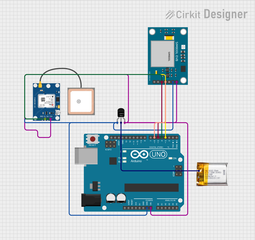
Circuit Documentation
Summary
This circuit involves multiple Arduino UNO microcontrollers, a GPS NEO 6M module, a SIM800L EVB GSM module, a 3.7V LiPo battery, and a Voltage Regulator. The primary function of this circuit is to read GPS data and send the coordinates via SMS using the GSM module. The circuit is powered by a 3.7V LiPo battery regulated to the required voltage levels.
Component List
Arduino UNO
- Description: A microcontroller board based on the ATmega328P.
- Pins: UNUSED, IOREF, Reset, 3.3V, 5V, GND, Vin, A0, A1, A2, A3, A4, A5, SCL, SDA, AREF, D13, D12, D11, D10, D9, D8, D7, D6, D5, D4, D3, D2, D1, D0
GPS NEO 6M
- Description: A GPS module used for receiving GPS signals.
- Pins: VCC, RX, TX, GND
3.7V LiPo
- Description: A 3.7V Lithium Polymer battery used for powering the circuit.
- Pins: +Ve, GND
Voltage Regulator
- Description: A component used to regulate the voltage from the LiPo battery to the required levels.
- Pins: GND, IN, OUT
SIM800L EVB GSM
- Description: A GSM module used for sending SMS.
- Pins: RST, GND, TXD, RXD, VDD, VCC
Wiring Details
Arduino UNO
GND connected to:
- GPS NEO 6M (GND)
- SIM800L EVB GSM (GND)
- Voltage Regulator (GND)
Vin connected to:
- GPS NEO 6M (VCC)
- SIM800L EVB GSM (VCC)
- Voltage Regulator (OUT)
D6 connected to:
- SIM800L EVB GSM (RXD)
D5 connected to:
- SIM800L EVB GSM (TXD)
D4 connected to:
- GPS NEO 6M (RX)
D3 connected to:
- GPS NEO 6M (TX)
GPS NEO 6M
GND connected to:
- Arduino UNO (GND)
- SIM800L EVB GSM (GND)
- Voltage Regulator (GND)
VCC connected to:
- Arduino UNO (Vin)
- SIM800L EVB GSM (VCC)
- Voltage Regulator (OUT)
RX connected to:
- Arduino UNO (D4)
TX connected to:
- Arduino UNO (D3)
3.7V LiPo
- +Ve connected to:
- Voltage Regulator (IN)
Voltage Regulator
GND connected to:
- GPS NEO 6M (GND)
- Arduino UNO (GND)
- SIM800L EVB GSM (GND)
IN connected to:
- 3.7V LiPo (+Ve)
OUT connected to:
- GPS NEO 6M (VCC)
- Arduino UNO (Vin)
- SIM800L EVB GSM (VCC)
SIM800L EVB GSM
GND connected to:
- GPS NEO 6M (GND)
- Arduino UNO (GND)
- Voltage Regulator (GND)
VCC connected to:
- GPS NEO 6M (VCC)
- Arduino UNO (Vin)
- Voltage Regulator (OUT)
RXD connected to:
- Arduino UNO (D6)
TXD connected to:
- Arduino UNO (D5)
Documented Code
Arduino UNO (Primary Microcontroller)
#include <SoftwareSerial.h>

// GPS module connections
SoftwareSerial gpsSerial(3, 4); // RX, TX

// GSM module connections
SoftwareSerial gsmSerial(5, 6); // RX, TX

void setup() {
  // Initialize serial communications
  Serial.begin(9600);
  gpsSerial.begin(9600);
  gsmSerial.begin(9600);

  // Initialize GSM module
  gsmSerial.println("AT");
  delay(1000);
  gsmSerial.println("AT+CMGF=1"); // Set SMS to text mode
  delay(1000);
}

void loop() {
  // Read data from GPS module
  if (gpsSerial.available()) {
    String gpsData = gpsSerial.readStringUntil('\n');
    Serial.println(gpsData);

    // Extract GPS coordinates from gpsData
    String latitude = extractLatitude(gpsData);
    String longitude = extractLongitude(gpsData);

    // Send GPS coordinates via SMS
    sendSMS(latitude, longitude);
  }

  delay(10000); // Wait for 10 seconds before next reading
}

String extractLatitude(String gpsData) {
  // Implement GPS data parsing to extract latitude
  return "latitude";
}

String extractLongitude(String gpsData) {
  // Implement GPS data parsing to extract longitude
  return "longitude";
}

void sendSMS(String latitude, String longitude) {
  gsmSerial.println("AT+CMGS=\"+1234567890\""); // Replace with your phone number
  delay(1000);
  gsmSerial.print("GPS Coordinates: ");
  gsmSerial.print("Latitude: ");
  gsmSerial.print(latitude);
  gsmSerial.print(", Longitude: ");
  gsmSerial.print(longitude);
  delay(1000);
  gsmSerial.write(26); // ASCII code for CTRL+Z to send the SMS
  delay(1000);
}
Other Arduino UNO Microcontrollers
void setup() {
  // put your setup code here, to run once:

}

void loop() {
  // put your main code here, to run repeatedly:

}
This concludes the documentation for the circuit.