
Arduino Mega 2560-Based Reverse Vending Machine with GSM and Wi-Fi Connectivity
View and Edit Project In Cirkit Designer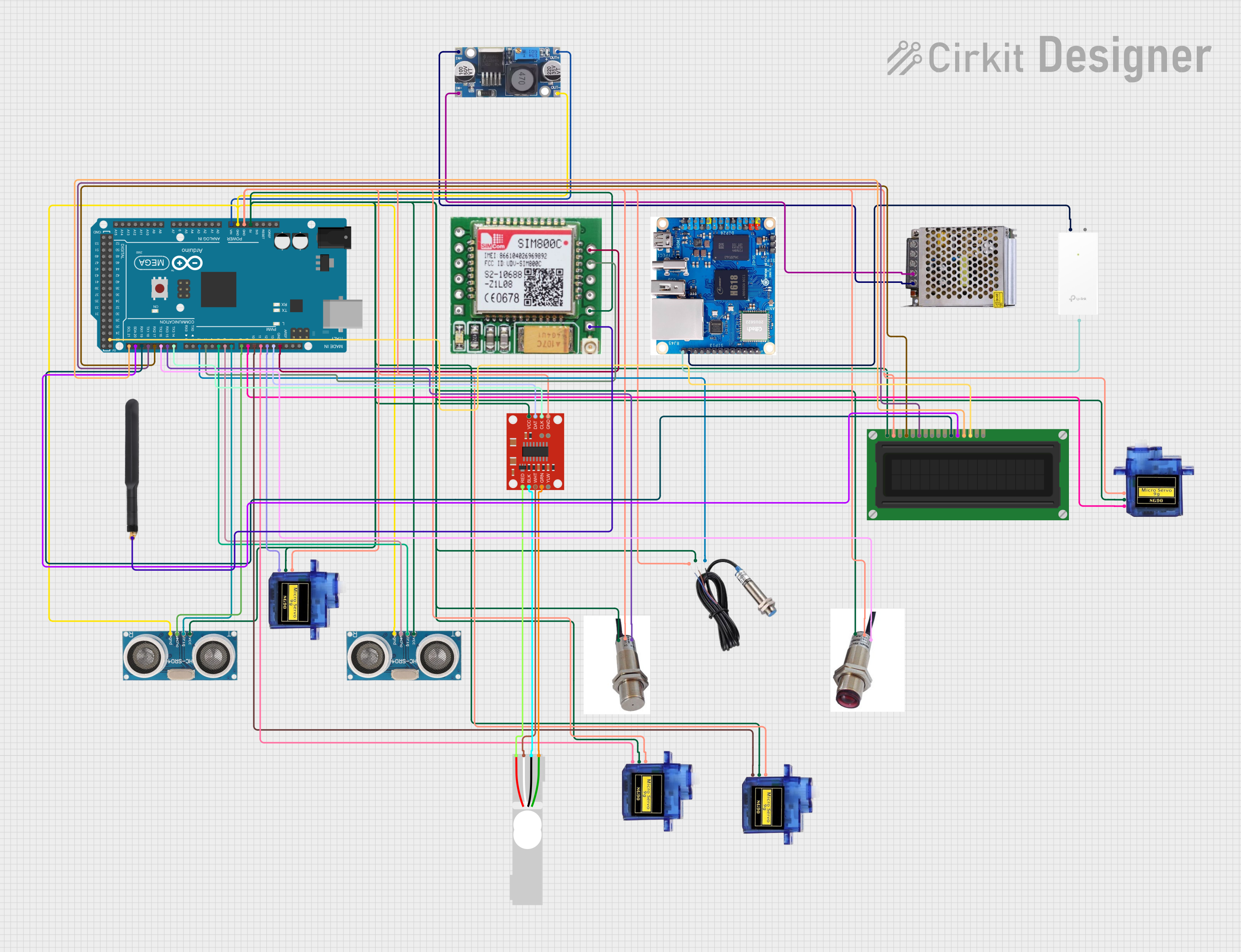
Circuit Documentation
Summary
This document provides a detailed overview of a circuit designed for a Plastic Bottle and Can Reverse Vending Machine. The circuit interfaces with various sensors and actuators to segregate plastic bottles and cans, and provides WiFi access for data transmission. The main components used in this circuit include an Arduino Mega 2560, ultrasonic sensors, load cell, micro servos, GSM module, LCD display, inductive and photoelectric sensors, and a power supply.
Component List
POWER SUPPLY 12V 5AMP
- Description: Provides 12V DC power to the circuit.
- Pins: 220V Positive Pole (AC), 220V Negative Pole (AC), GND, GND (DC), 12V-24V Output (DC)
Arduino Mega 2560
- Description: Main microcontroller used for controlling the circuit.
- Pins: IOREF, RESET, 3V3, 5V, GND, VIN, A0-A15, D0-D53, AREF, SDA, SCL
Load Cell - Red/white/black/green
- Description: Measures weight of objects.
- Pins: E+, A-, E-, A+
Micro servo 9G
- Description: Actuates mechanical movements.
- Pins: GND, +5V, PWM
Ultrasonic Sensor
- Description: Measures distance to objects.
- Pins: +VCC, Trigger, Echo, GND
Orange Pi Zero 3
- Description: Provides WiFi access and additional processing power.
- Pins: TX, RX, GND, 5V IO, USB2DM, USB2DP, USB3DM, IR/RX, PI6, PI16, PC1, TV/OUT, LR, LL, USB3 DP, 3.3V OUT/GPIO1, 5V IO/GPIO2, I2C3 SDA/PH5/GPIO3, 5V IO/GPIO4, I2C3 SCK/PH4/GPIO5, PC9/GPIO7, UART TX/PH2/GPIO8, UART RX/PH3/GPIO10, PC6/GPIO11, PC11/GPIO12, PC5/GPIO13, PC8/GPIO15, PC15/GPIO16, 3.3V OUT, PC14/GPIO18, SPI1 MOSI/PH7/GPIO19, SPI1 MISO/PH8/GPIO21, PC7/GPIO22, SPI1 CLK/PH6/GPIO23, SPI1/CS/PH9/GPIO24, PC10/GPIO26
Step down Buck converter
- Description: Converts 12V DC to 5V DC.
- Pins: IN +, IN - GND, OUT +, OUT - GND
SparkFun Load Cell Amplifier - HX711
- Description: Amplifies the signal from the load cell.
- Pins: GND, CLK, DAT, VCC, YLW, GRN, WHT, BLK, RED, B-, B+
Inductive Sensor
- Description: Detects metallic objects.
- Pins: Signal, VCC, GND
Laser Beam Photoelectric Sensor (receiver)
- Description: Detects objects using a laser beam.
- Pins: VCC, GND, Signal (Out)
LCD Display (16 pin)
- Description: Displays information to the user.
- Pins: VSS, VDD, VO, RS, R_W, E, DB0-DB7, A, K
TP-Link Router
- Description: Provides WiFi connectivity.
- Pins: Power, POE, LAN
Laser Beam Photoelectric Sensor (inductor)
- Description: Detects objects using a laser beam.
- Pins: VCC, GND, Signal
SIM800c GSM Module
- Description: Provides GSM communication.
- Pins: SPK-, SPK+, MIC-, MIC+, DTR, RING, GND, TXD, RXD, LINK GND, ANT, VCC(3.7 - 4.2)
4G Antenna
- Description: Enhances GSM signal.
- Pins: Connection
Wiring Details
POWER SUPPLY 12V 5AMP
- GND (DC) connected to Step down Buck converter IN - GND
- 12V-24V Output (DC) connected to Step down Buck converter IN +
Step down Buck converter
- IN - GND connected to POWER SUPPLY 12V 5AMP GND (DC)
- IN + connected to POWER SUPPLY 12V 5AMP 12V-24V Output (DC)
- OUT - GND connected to Arduino Mega 2560 GND, Ultrasonic Sensor GND, SparkFun Load Cell Amplifier - HX711 GND, Micro servo 9G GND, Inductive Sensor GND, Laser Beam Photoelectric Sensor (receiver) GND, Laser Beam Photoelectric Sensor (inductor) GND
- OUT + connected to Arduino Mega 2560 VIN
Arduino Mega 2560
- 5V connected to Micro servo 9G +5V, Ultrasonic Sensor +VCC, LCD Display (16 pin) VSS, Laser Beam Photoelectric Sensor (inductor) VCC, SIM800c GSM Module VCC(3.7 - 4.2), Laser Beam Photoelectric Sensor (receiver) VCC, SparkFun Load Cell Amplifier - HX711 VCC, Inductive Sensor VCC
- GND connected to Step down Buck converter OUT - GND, SIM800c GSM Module GND
- VIN connected to Step down Buck converter OUT +
- D21/SCL connected to LCD Display (16 pin) DB6
- D20/SDA connected to LCD Display (16 pin) DB5
- D19/RX1 connected to LCD Display (16 pin) DB4
- D18/TX1 connected to LCD Display (16 pin) E
- D17 PWM/RX2 connected to LCD Display (16 pin) RS
- D16 PWM/TX2 connected to Laser Beam Photoelectric Sensor (receiver) Signal (Out)
- D15/RX3 connected to Laser Beam Photoelectric Sensor (inductor) Signal
- D14/TX3 connected to SparkFun Load Cell Amplifier - HX711 CLK
- D2 PWM connected to Inductive Sensor Signal
- D3 PWM connected to SIM800c GSM Module TXD
- D5 PWM connected to Ultrasonic Sensor Trigger
- D6 PWM connected to Ultrasonic Sensor Echo
- D7 PWM connected to Ultrasonic Sensor Trigger
- D8 PWM connected to Ultrasonic Sensor Echo
- D9 PWM connected to Micro servo 9G PWM
- D10 PWM connected to Micro servo 9G PWM
- D11 PWM connected to Micro servo 9G PWM
- D12 PWM connected to Micro servo 9G PWM
- D13 PWM connected to SparkFun Load Cell Amplifier - HX711 DAT
- D22 connected to LCD Display (16 pin) DB7
Ultrasonic Sensor
- +VCC connected to Arduino Mega 2560 5V
- GND connected to Step down Buck converter OUT - GND
- Trigger connected to Arduino Mega 2560 D5 PWM, Arduino Mega 2560 D7 PWM
- Echo connected to Arduino Mega 2560 D6 PWM, Arduino Mega 2560 D8 PWM
Load Cell - Red/white/black/green
- A+ connected to SparkFun Load Cell Amplifier - HX711 GRN
- A- connected to SparkFun Load Cell Amplifier - HX711 WHT
- E- connected to SparkFun Load Cell Amplifier - HX711 BLK
- E+ connected to SparkFun Load Cell Amplifier - HX711 RED
Micro servo 9G
- GND connected to Step down Buck converter OUT - GND
- +5V connected to Arduino Mega 2560 5V
- PWM connected to Arduino Mega 2560 D9 PWM, Arduino Mega 2560 D10 PWM, Arduino Mega 2560 D11 PWM, Arduino Mega 2560 D12 PWM
SparkFun Load Cell Amplifier - HX711
- GND connected to Step down Buck converter OUT - GND
- VCC connected to Arduino Mega 2560 5V
- DAT connected to Arduino Mega 2560 D13 PWM
- CLK connected to Arduino Mega 2560 D14/TX3
- GRN connected to Load Cell - Red/white/black/green A+
- WHT