Cirkit Designer
Your all-in-one circuit design IDE
Home /
Project Documentation
Arduino-Controlled Environment Monitoring and Stepper Motor Driver System

Circuit Documentation
Summary of the Circuit
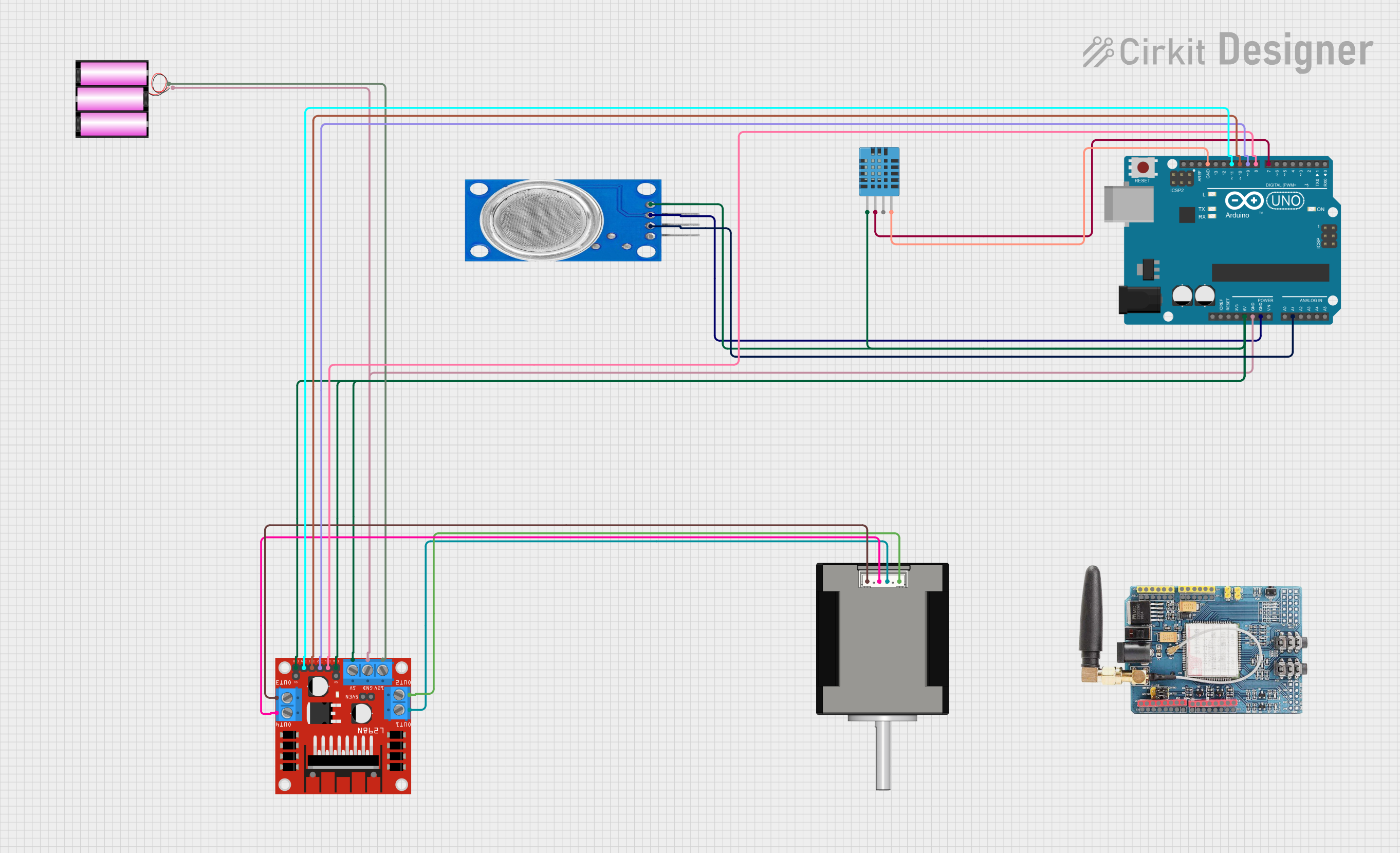
This circuit integrates various components to perform multiple functions. It includes sensors for environmental monitoring, a microcontroller for processing and control, a motor driver to control a stepper motor, and a GSM module for communication capabilities. The power supply is provided by a 12V battery, and the Arduino UNO microcontroller is the central processing unit that interfaces with all other components.
Component List
MQ135 Air Quality Sensor
- Pins: VCC, GND, A0, D0
- Description: This sensor is used for monitoring air quality by detecting various gases in the air.
Nema 17 42-STH48 Stepper Motor
- Pins: A2 (black), A1 (green), B2 (red), B1 (blue)
- Description: A stepper motor used for precise control of angular or linear position, velocity, and acceleration.
12V Battery
- Pins: +, -
- Description: Provides the power supply for the circuit.
Arduino UNO
- Pins: UNUSED, IOREF, Reset, 3.3V, 5V, GND, Vin, A0-A5, SCL, SDA, AREF, D0-D13
- Description: A microcontroller board based on the ATmega328P, used for controlling the logic of the circuit.
DHT11 Humidity and Temperature Sensor
- Pins: VDD, DATA, NULL, GND
- Description: Measures ambient temperature and humidity.
L298N DC Motor Driver
- Pins: OUT1-OUT4, 12V, GND, 5V, ENA, ENB, IN1-IN4
- Description: An integrated circuit used to control the stepper motor.
GSM SIM900 Module
- Pins: A0-A5, 5V, GND, 3.3V, RESET, D0-D13, AREF
- Description: A GSM/GPRS module for cellular communication.
Wiring Details
MQ135 Air Quality Sensor
- VCC connected to Arduino UNO 5V
- GND connected to Arduino UNO GND
- A0 connected to Arduino UNO A1
Nema 17 42-STH48 Stepper Motor
- A2 (black) connected to L298N DC motor driver OUT2
- A1 (green) connected to L298N DC motor driver OUT1
- B2 (red) connected to L298N DC motor driver OUT4
- B1 (blue) connected to L298N DC motor driver OUT3
12V Battery
- + connected to L298N DC motor driver 12V
- - connected to Arduino UNO GND and L298N DC motor driver GND
Arduino UNO
- 5V connected to DHT11 VDD, L298N DC motor driver 5V, and MQ135 VCC
- GND connected to DHT11 GND, MQ135 GND, and L298N DC motor driver GND
- A1 connected to MQ135 A0
- D7 connected to DHT11 DATA
- D8-D11 connected to L298N DC motor driver IN1-IN4
DHT11 Humidity and Temperature Sensor
- VDD connected to Arduino UNO 5V
- DATA connected to Arduino UNO D7
- GND connected to Arduino UNO GND
L298N DC Motor Driver
- ENA, ENB connected to Arduino UNO 5V
- IN1-IN4 connected to Arduino UNO D8-D11
- OUT1-OUT4 connected to Nema 17 42-STH48
- 12V connected to 12V Battery +
- GND connected to 12V Battery - and Arduino UNO GND
- 5V connected to Arduino UNO 5V
Documented Code
Arduino UNO Code (sketch.ino)
void setup() {
  // put your setup code here, to run once:

}

void loop() {
  // put your main code here, to run repeatedly:

}
Note: The provided code is a template and does not include specific functionality. It should be populated with the logic required to control the components in the circuit based on the desired application.