
Arduino and NodeMCU-Based Smart Sensor System with LCD Display and Wi-Fi Connectivity
View and Edit Project In Cirkit Designer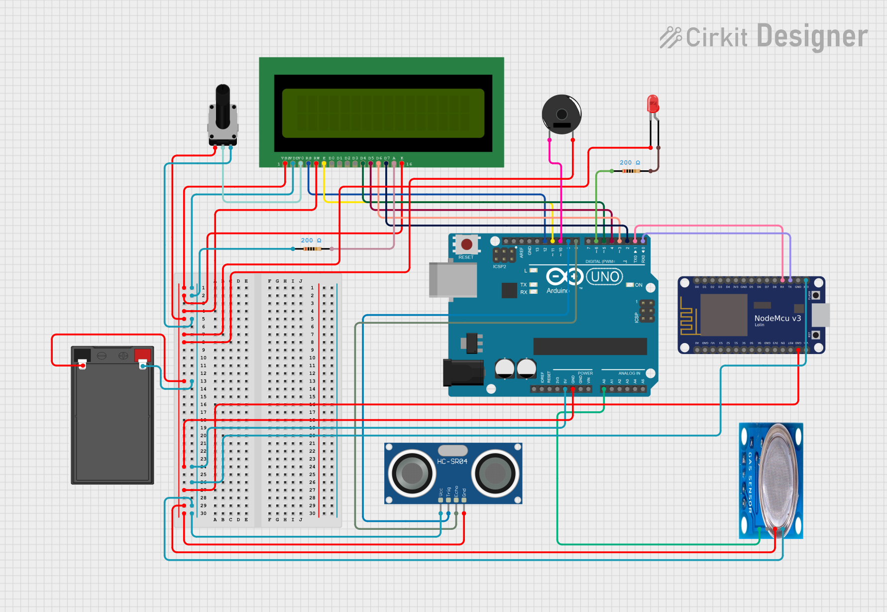
Circuit Documentation
Summary
This circuit integrates various components including a NodeMCU V3 ESP8266, an Arduino UNO, an HC-SR04 Ultrasonic Sensor, an MQ-5 gas sensor, an LCD 16x2 display, a rotary potentiometer, a red LED, a piezo buzzer, and a battery. The circuit is designed to interface these components to perform specific tasks, with the Arduino UNO acting as the primary microcontroller.
Component List
NodeMCU V3 ESP8266
- Pins: A0, GND, VU, S3, S2, S1, SC, S0, SK, 3V3, EN, RST, Vin, D0, D1, D2, D3, D4, D5, D6, D7, D8, RX, TX
- Description: A low-cost Wi-Fi microcontroller with GPIO, ADC, and PWM capabilities.
HC-SR04 Ultrasonic Sensor
- Pins: VCC, TRIG, ECHO, GND
- Description: A sensor used to measure distance using ultrasonic waves.
MQ-5 Gas Sensor
- Pins: VCC, GND, Digi Out, Analog out
- Description: A gas sensor used to detect LPG, natural gas, and coal gas.
Battery
- Pins: -, +
- Description: Provides power to the circuit.
LED: Two Pin (red)
- Pins: Cathode, Anode
- Description: A red LED used for visual indication.
Piezo Buzzer
- Pins: Pin 1, Pin 2
- Description: A buzzer used for sound indication.
LCD 16x2 (Wokwi Compatible)
- Pins: VSS, VDD, V0, RS, RW, E, D0, D1, D2, D3, D4, D5, D6, D7, A, K
- Description: A 16x2 character LCD display.
Rotary Potentiometer
- Pins: Leg1, Wiper, Leg2
- Description: A variable resistor used to adjust voltage.
- Properties: Resistance: 10k Ohms
Arduino UNO
- Pins: UNUSED, IOREF, Reset, 3.3V, 5V, GND, Vin, A0, A1, A2, A3, A4, A5, SCL, SDA, AREF, D13, D12, D11, D10, D9, D8, D7, D6, D5, D4, D3, D2, D1, D0
- Description: A popular microcontroller board based on the ATmega328P.
Resistor (200 Ohms)
- Pins: Pin1, Pin2
- Description: A resistor used to limit current.
- Properties: Resistance: 200 Ohms
Wiring Details
NodeMCU V3 ESP8266
- GND connected to the common ground.
- 3V3 connected to the 5V power rail.
- RX connected to Arduino UNO D1.
- TX connected to Arduino UNO D0.
HC-SR04 Ultrasonic Sensor
- VCC connected to the 5V power rail.
- GND connected to the common ground.
- TRIG connected to Arduino UNO D9.
- ECHO connected to Arduino UNO D8.
MQ-5 Gas Sensor
- VCC connected to the 5V power rail.
- GND connected to the common ground.
- Analog out connected to Arduino UNO A0.
Battery
- - connected to the common ground.
- + connected to the 5V power rail.
LED: Two Pin (red)
- Cathode connected to the common ground.
- Anode connected to Resistor pin2.
Piezo Buzzer
- Pin 1 connected to Arduino UNO D10.
- Pin 2 connected to the common ground.
LCD 16x2 (Wokwi Compatible)
- VSS connected to the common ground.
- VDD connected to the 5V power rail.
- V0 connected to Rotary Potentiometer wiper.
- RS connected to Arduino UNO D12.
- RW connected to the common ground.
- E connected to Arduino UNO D11.
- D4 connected to Arduino UNO D5.
- D5 connected to Arduino UNO D4.
- D6 connected to Arduino UNO D3.
- D7 connected to Arduino UNO D2.
- A connected to Resistor pin2.
- K connected to the common ground.
Rotary Potentiometer
- Leg1 connected to the common ground.
- Wiper connected to LCD 16x2 V0.
- Leg2 connected to the 5V power rail.
Arduino UNO
- GND connected to the common ground.
- 5V connected to the 5V power rail.
- A0 connected to MQ-5 Analog out.
- D0 connected to NodeMCU V3 ESP8266 TX.
- D1 connected to NodeMCU V3 ESP8266 RX.
- D2 connected to LCD 16x2 D7.
- D3 connected to LCD 16x2 D6.
- D4 connected to LCD 16x2 D5.
- D5 connected to LCD 16x2 D4.
- D6 connected to Resistor pin1.
- D8 connected to HC-SR04 ECHO.
- D9 connected to HC-SR04 TRIG.
- D10 connected to Piezo Buzzer pin 1.
- D11 connected to LCD 16x2 E.
- D12 connected to LCD 16x2 RS.
Resistor (200 Ohms)
- Pin1 connected to Arduino UNO D6.
- Pin2 connected to LED Anode.
- Pin1 connected to the 5V power rail.
- Pin2 connected to LCD 16x2 A.
Documented Code
Arduino UNO Code (sketch.ino)
void setup() {
  // put your setup code here, to run once:

}

void loop() {
  // put your main code here, to run repeatedly:

}
Documentation (documentation.txt)
This documentation provides a comprehensive overview of the circuit, including a summary, detailed component list, wiring details, and the code used in the microcontroller.