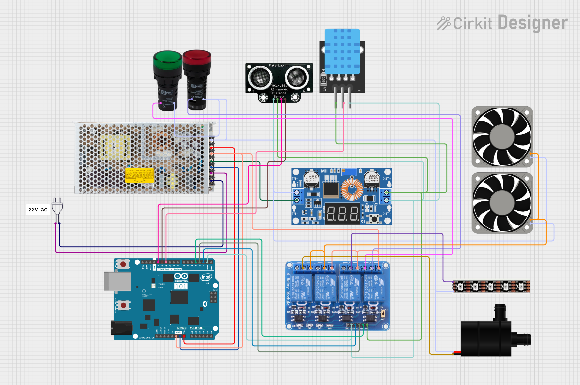
Arduino-Controlled Relay System with Ultrasonic Sensing and Temperature Monitoring

Circuit Documentation
Summary
This circuit is designed to control various devices, including a relay module, ultrasonic distance sensor, temperature sensor, LED strip, pilot lamps, fans, and a water pump. The central control unit is an Arduino 101 microcontroller, which interfaces with the sensors and controls the relay module to switch the connected devices. The circuit is powered by a switching power supply that converts 220V AC to a DC voltage, which is then stepped down by a DC buck converter to supply the necessary voltage levels to the components.
Component List
Arduino 101
- Microcontroller board based on the Intel Curie module.
- Provides various digital I/O pins and analog inputs.
- Capable of PWM output and I2C communication.
Relay 4 Channel 5v
- A 4-channel relay module with both normally open (NO) and normally closed (NC) contacts.
- Controlled by digital signals to switch connected devices on and off.
Switching Power Supply
- Converts 220V AC power to a DC voltage.
- Provides a ground reference and positive voltage output.
Power 220V
- Represents the main AC power input to the circuit.
XL4015 5A DC Buck Step-down
- A DC-DC step-down (buck) converter module.
- Steps down the voltage to a lower level suitable for the circuit components.
MKE-S01 Ultrasonic Distance Sensor
- Measures distances by emitting ultrasonic waves and measuring the time taken for the echo to return.
TEMP (Temperature Sensor)
- Senses the temperature of the environment.
Pilot Lamp Red
- An indicator lamp that lights up red when powered.
Pilot Lamp Green
- An indicator lamp that lights up green when powered.
40 Fan 12V
- A 12V DC fan used for cooling purposes.
Water Pump
- A DC water pump used to circulate or move water.
WS2815 LED Strip
- An LED strip with individually addressable RGB LEDs.
Wiring Details
Arduino 101
D13/SCKconnected to Ultrasonic Distance Sensor TRIG pin.D12/MISOconnected to Ultrasonic Distance Sensor ECHO pin.D11 PWM/MOSIconnected to TEMP D3 pin.D4connected to Relay 4 Channel 5v IN4 pin.D3 PWMconnected to Relay 4 Channel 5v IN3 pin.D2connected to Relay 4 Channel 5v IN2 pin.D1/TXconnected to Relay 4 Channel 5v IN1 pin.GNDconnected to the ground net of the circuit.VINconnected to the positive voltage from the Switching Power Supply.
Relay 4 Channel 5v
IN1,IN2,IN3,IN4controlled by Arduino 101.VCCconnected to the positive output from the XL4015 5A DC Buck Step-down.GNDconnected to the ground net of the circuit.COM1connected to Water Pump GND.NO1,NO2,NO3,NO4connected to the negative voltage from the Switching Power Supply.NC4connected to Pilot Lamp Green X1 pin.
Switching Power Supply
ACconnected to Power 220V hot and neutral wires.GNDconnected to the ground net of the circuit.-Vconnected to the negative voltage net of the circuit.+Vconnected to the positive voltage net of the circuit.
XL4015 5A DC Buck Step-down
Input +connected to the positive voltage from the Switching Power Supply.Input -connected to the negative voltage from the Switching Power Supply.Output +connected to the positive voltage net of the circuit.Output -connected to the ground net of the circuit.
MKE-S01 Ultrasonic Distance Sensor
5Vconnected to the positive output from the XL4015 5A DC Buck Step-down.GNDconnected to the ground net of the circuit.TRIGconnected to Arduino 101 D13/SCK pin.ECHOconnected to Arduino 101 D12/MISO pin.
TEMP (Temperature Sensor)
5Vconnected to the positive output from the XL4015 5A DC Buck Step-down.D3connected to Arduino 101 D11 PWM/MOSI pin.GNDconnected to the ground net of the circuit.
Pilot Lamp Red
X1connected to Relay 4 Channel 5v COM4 pin.X2connected to the positive voltage net of the circuit.
Pilot Lamp Green
X1connected to Relay 4 Channel 5v NC4 pin.X2connected to the positive voltage net of the circuit.
40 Fan 12V
+12Vconnected to the positive voltage net of the circuit.-12Vconnected to Relay 4 Channel 5v NO1 pin.
Water Pump
VCCconnected to the positive voltage net of the circuit.GNDconnected to Relay 4 Channel 5v COM1 pin.
WS2815 LED Strip
+12Vconnected to the positive voltage net of the circuit.GNDconnected to Relay 4 Channel 5v COM3 pin.B0andD0not connected in the provided net list.
Documented Code
No code was provided for the microcontrollers in the circuit. The documentation of the code would include descriptions of the functions, initialization routines, main loop, and any interrupt service routines or additional functions used to control the hardware components based on the inputs and sensor data.