
Arduino Mega 2560 Controlled LED and Motor System with Battery Power
View and Edit Project In Cirkit Designer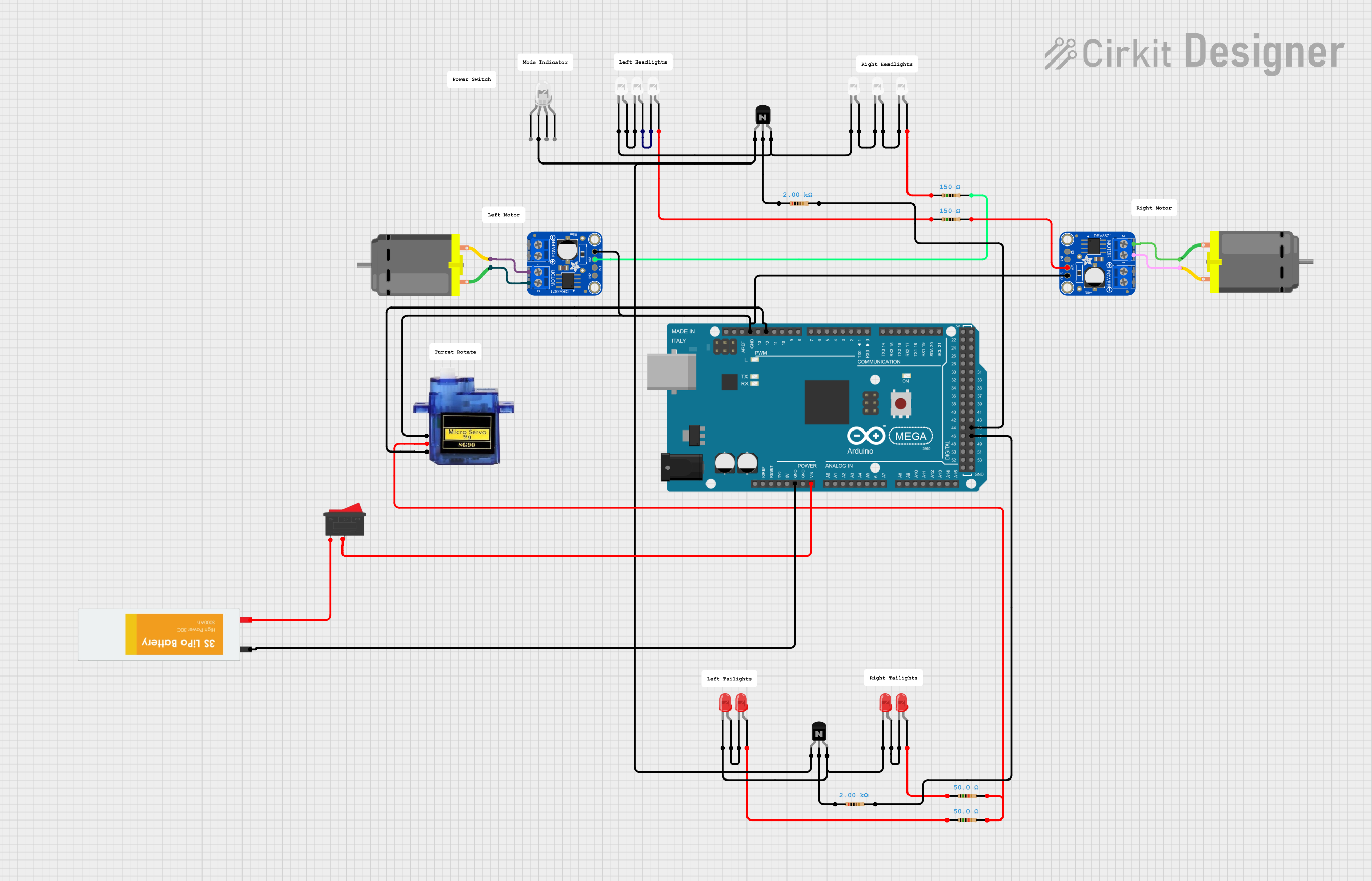
Circuit Documentation
Summary
This circuit consists of multiple LEDs (both red and white), resistors, NPN transistors, a motor driver, DC motors, a micro servo, a rocker switch, and an Arduino Mega 2560 microcontroller. The circuit is designed to control the LEDs, motors, and servo using the Arduino Mega 2560.
Component List
LED: Two Pin (red)
- Pins: cathode, anode
- Description: Red LED with two pins.
LED: Two Pin (white)
- Pins: cathode, anode
- Description: White LED with two pins.
Resistor
- Pins: pin1, pin2
- Description: Resistor with varying resistance values.
- Properties:
- Resistance: 50 Ohms, 150 Ohms, 2000 Ohms
NPN Transistor (ECB)
- Pins: emitter, collector, base
- Description: NPN transistor with three pins.
Adafruit DRV8871
- Pins: GND, VMOTOR, IN1, IN2, OUT1, OUT2
- Description: Motor driver.
DC Motor
- Pins: pin 1, pin 2
- Description: DC motor with two pins.
Micro servo 9G
- Pins: GND, +5V, PWM
- Description: Micro servo motor.
Rocker Switch
- Pins: 1, 2
- Description: Rocker switch with two pins.
LED: Four Pin
- Pins: red cathode, common anode, green cathode, blue cathode
- Description: Four-pin LED with multiple color options.
Arduino Mega 2560
- Pins: IOREF, RESET, 3V3, 5V, GND, VIN, A0-A15, D0-D53, PWM pins, AREF, SDA, SCL
- Description: Microcontroller board.
Lipo Battery
- Pins: VCC, GND
- Description: Lithium polymer battery.
Wiring Details
LED: Two Pin (red)
- Cathode connected to the base of the NPN Transistor (ECB).
- Anode connected to the cathode of another red LED.
LED: Two Pin (white)
- Anode connected to the cathode of another white LED.
- Cathode connected to the base of the NPN Transistor (ECB).
Resistor
- Pin1 connected to the anode of the red LED.
- Pin2 connected to the VMOTOR pin of the Adafruit DRV8871.
NPN Transistor (ECB)
- Emitter connected to the common anode of the four-pin LED.
- Collector connected to the pin1 of the resistor.
- Base connected to the cathode of the white LED.
Adafruit DRV8871
- GND connected to the GND of the Arduino Mega 2560.
- VMOTOR connected to the pin2 of the resistor.
- OUT1 connected to the pin2 of the DC Motor.
- OUT2 connected to the pin1 of the DC Motor.
DC Motor
- Pin 1 connected to the OUT2 of the Adafruit DRV8871.
- Pin 2 connected to the OUT1 of the Adafruit DRV8871.
Micro servo 9G
- GND connected to the GND of the Arduino Mega 2560.
- +5V connected to the pin2 of the resistor.
- PWM connected to the D12 PWM pin of the Arduino Mega 2560.
Rocker Switch
- Pin 1 connected to the VCC of the Lipo Battery.
- Pin 2 connected to the VIN of the Arduino Mega 2560.
LED: Four Pin
- Common Anode connected to the emitter of the NPN Transistor (ECB).
Arduino Mega 2560
- GND connected to the GND of the Lipo Battery.
- VIN connected to the pin2 of the Rocker Switch.
- D12 PWM connected to the PWM pin of the Micro servo 9G.
Lipo Battery
- VCC connected to the pin1 of the Rocker Switch.
- GND connected to the GND of the Arduino Mega 2560.
Code Documentation
Arduino Mega 2560 Code
File Name: sketch.ino
void setup() {
  // put your setup code here, to run once:

}

void loop() {
  // put your main code here, to run repeatedly:

}
File Name: documentation.txt
// This file is intended for documentation purposes.
This documentation provides a comprehensive overview of the circuit, including a detailed component list, wiring details, and the code used for the Arduino Mega 2560 microcontroller.