ESP8266 Controlled Robot with L298N Motor Driver and Ultrasonic Sensor
Circuit Documentation
Summary
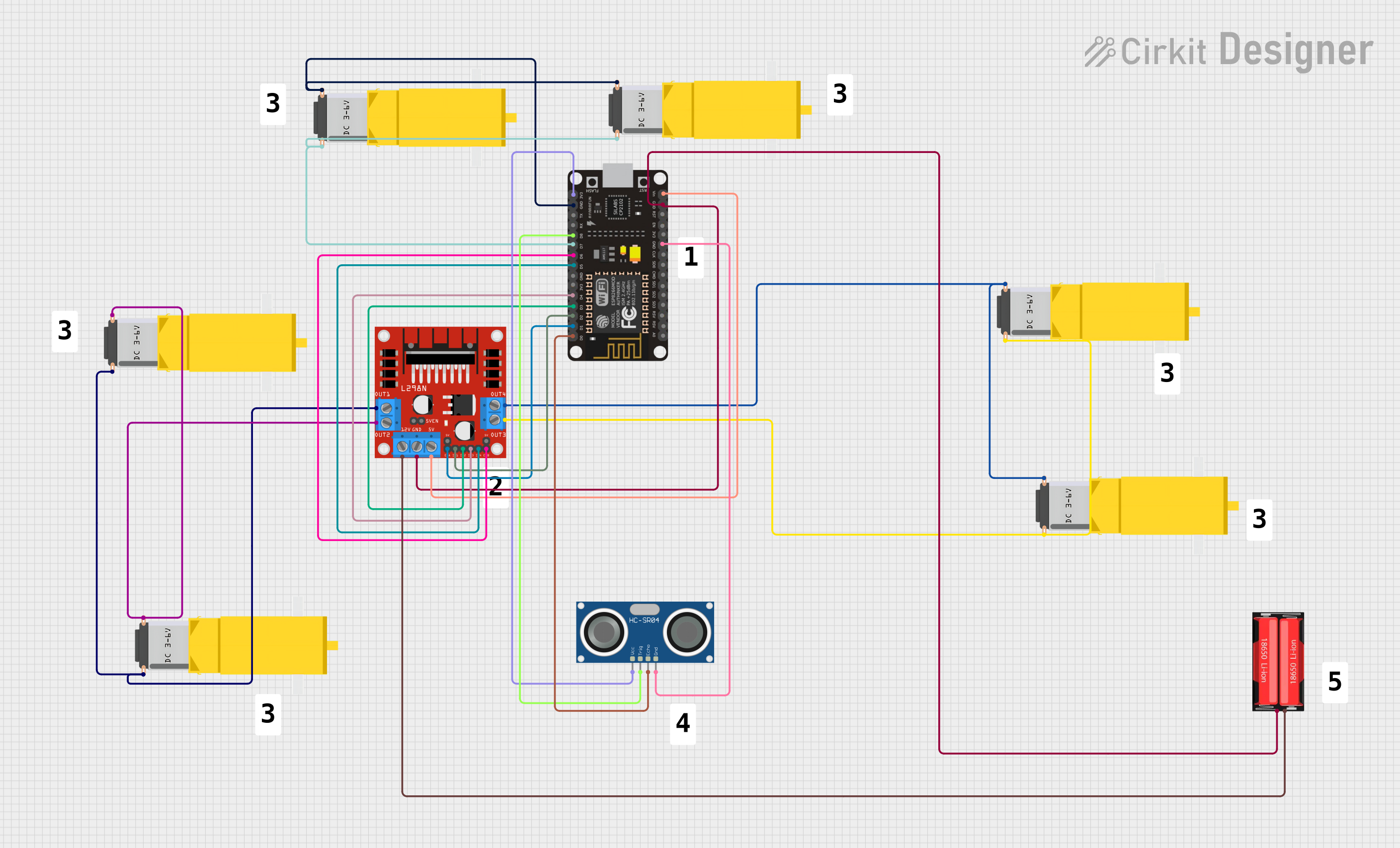
This circuit is designed to control multiple DC gearmotors using an L298N DC motor driver, which is interfaced with an ESP8266 NodeMCU microcontroller. The circuit also includes an HC-SR04 Ultrasonic Sensor for distance measurement and an 18650 Li-Ion battery for power supply. The ESP8266 NodeMCU is programmed to manage the motor driver inputs and to read signals from the ultrasonic sensor.
Component List
Gearmotor DC / Motorreductor
- Description: A DC gearmotor used for providing rotational motion.
- Pins: Pin1, Pin2
18650 Li-Ion Battery
- Description: A rechargeable lithium-ion battery used as the power source for the circuit.
- Pins: Positive, Negative
L298N DC Motor Driver
- Description: A motor driver module capable of driving two DC motors or one stepper motor.
- Pins: OUT1, OUT2, 12V, GND, 5V, OUT3, OUT4, 5V-ENA-JMP-I, 5V-ENA-JMP-O, +5V-J1, +5V-J2, ENA, IN1, IN2, IN3, IN4, ENB
ESP8266 NodeMCU
- Description: A Wi-Fi enabled microcontroller used for controlling the motor driver and reading sensor data.
- Pins: D0, D1, D2, D3, D4, 3V3, GND, D5, D6, D7, D8, RX, TX, A0, RSV, SD3, SD2, SD1, CMD, SD0, CLK, EN, RST, VIN
HC-SR04 Ultrasonic Sensor
- Description: An ultrasonic sensor used for measuring distances by emitting and receiving ultrasonic waves.
- Pins: VCC, TRIG, ECHO, GND
Wiring Details
Gearmotor DC / Motorreductor
- Pin1: Connected to L298N DC motor driver OUT2 or OUT4
- Pin2: Connected to L298N DC motor driver OUT1 or OUT3
18650 Li-Ion Battery
- Positive: Connected to L298N DC motor driver 12V
- Negative: Connected to L298N DC motor driver GND and ESP8266 NodeMCU GND
L298N DC Motor Driver
- OUT1, OUT2, OUT3, OUT4: Connected to Gearmotor DC / Motorreductor Pin1 and Pin2
- 12V: Connected to 18650 Li-Ion Battery Positive
- GND: Connected to 18650 Li-Ion Battery Negative and ESP8266 NodeMCU GND
- 5V: Connected to ESP8266 NodeMCU VIN
- ENA, ENB: Connected to ESP8266 NodeMCU D1 and D6 respectively
- IN1, IN2, IN3, IN4: Connected to ESP8266 NodeMCU D2, D3, D4, D5 respectively
ESP8266 NodeMCU
- VIN: Connected to L298N DC motor driver 5V
- GND: Connected to L298N DC motor driver GND and 18650 Li-Ion Battery Negative
- D0, D1, D2, D3, D4, D5, D6, D7, D8: Connected to L298N DC motor driver ENA, IN1, IN2, IN3, IN4, ENB, and HC-SR04 Ultrasonic Sensor TRIG
- 3V3: Connected to HC-SR04 Ultrasonic Sensor VCC
HC-SR04 Ultrasonic Sensor
- VCC: Connected to ESP8266 NodeMCU 3V3
- TRIG: Connected to ESP8266 NodeMCU D8
- ECHO: Connected to ESP8266 NodeMCU D0
- GND: Connected to ESP8266 NodeMCU GND
Documented Code
void setup() {
  // put your setup code here, to run once:

}

void loop() {
  // put your main code here, to run repeatedly:

}
The provided code is a template for the ESP8266 NodeMCU microcontroller. The setup() function is intended for initialization code that runs once at startup, and the loop() function contains code that runs continuously. The actual implementation should include configurations for the motor driver control pins and the ultrasonic sensor pins, as well as the logic for motor control and distance measurement.