
Arduino-Based Smart Bulb Control with GSM Module and Current Sensing
View and Edit Project In Cirkit Designer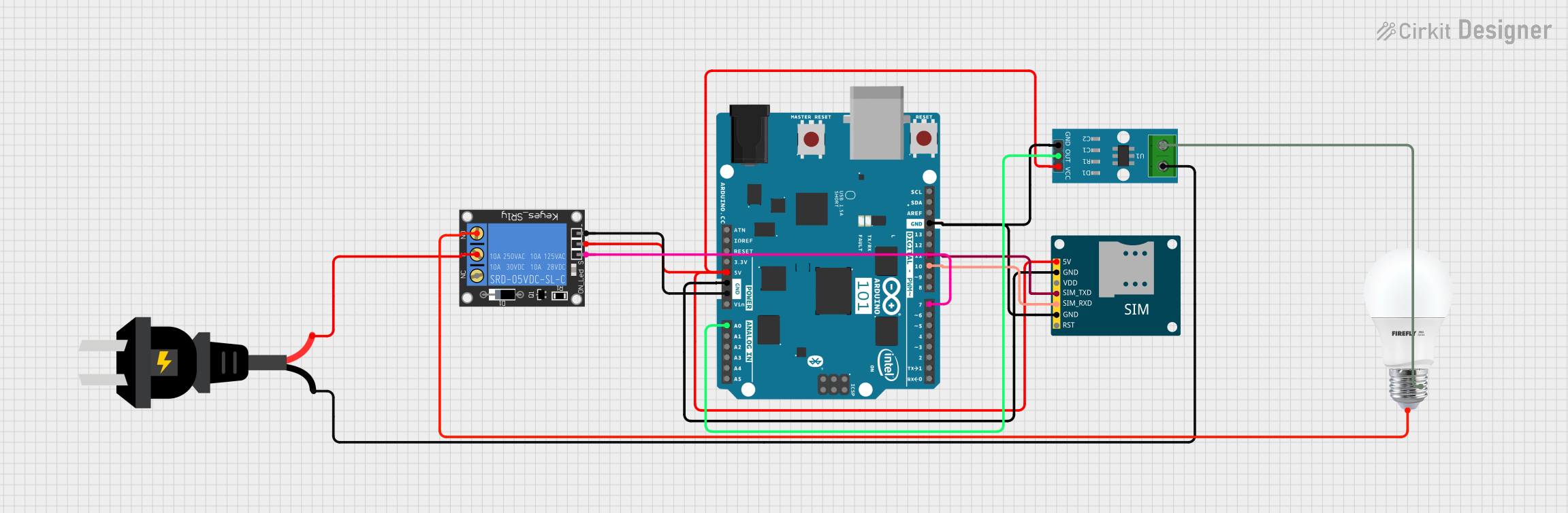
Circuit Documentation
Summary
This circuit integrates an Arduino 101 microcontroller, a SIM800L GSM module, an ACS712 current sensor, a 1-channel relay, an AC source, and a bulb. The Arduino 101 serves as the central controller, interfacing with the GSM module for communication, the current sensor for monitoring current, and the relay for controlling the bulb connected to the AC source.
Component List
Arduino 101
- Description: A microcontroller board based on the Intel Curie module.
- Pins: A5/SCL, A4/SDA, AREF, GND, D13/SCK, D12/MISO, D11 PWM/MOSI, D10 PWM/SS, D9 PWM, D8, D7, D6 PWM, D5 PWM, D4, D3 PWM, D2, D1/TX, D0/RX, AIN, ioref, RESET, 3V3, 5V, VIN, A0, A1, A2, A3, ICSP MISO, ICSP SCK, ICSP MOSI
SIM800L GSM Module
- Description: A GSM/GPRS module for communication over cellular networks.
- Pins: 5V, GND, VDD, SIM_TXD, SIM_RXD, RST
ACS712 Current Sensor 5A 20A 30A
- Description: A current sensor module for measuring current.
- Pins: 1, 2, GND, OUT, VCC
1-Channel Relay (5V 10A)
- Description: A relay module for switching high-power devices.
- Pins: NC, signal, C, power, NO, ground
AC Source
- Description: An AC power source.
- Pins: +, -
Bulb
- Description: A standard light bulb.
- Pins: +, -
Wiring Details
Arduino 101
- GND: Connected to GND of SIM800L GSM Module, ACS712 Current Sensor, and 1-Channel Relay.
- D11 PWM/MOSI: Connected to SIM_TXD of SIM800L GSM Module.
- D10 PWM/SS: Connected to SIM_RXD of SIM800L GSM Module.
- D7: Connected to signal pin of 1-Channel Relay.
- 5V: Connected to 5V of SIM800L GSM Module, power pin of 1-Channel Relay, and VCC of ACS712 Current Sensor.
- A0: Connected to OUT of ACS712 Current Sensor.
SIM800L GSM Module
- GND: Connected to GND of Arduino 101 and ACS712 Current Sensor.
- SIM_TXD: Connected to D11 PWM/MOSI of Arduino 101.
- SIM_RXD: Connected to D10 PWM/SS of Arduino 101.
- 5V: Connected to 5V of Arduino 101 and power pin of 1-Channel Relay.
ACS712 Current Sensor 5A 20A 30A
- GND: Connected to GND of Arduino 101 and SIM800L GSM Module.
- OUT: Connected to A0 of Arduino 101.
- VCC: Connected to 5V of Arduino 101 and SIM800L GSM Module.
- 1: Connected to - of AC source.
- 2: Connected to - of Bulb.
1-Channel Relay (5V 10A)
- signal: Connected to D7 of Arduino 101.
- power: Connected to 5V of Arduino 101 and SIM800L GSM Module.
- ground: Connected to GND of Arduino 101.
- C: Connected to + of AC source.
- NO: Connected to + of Bulb.
AC Source
- +: Connected to C of 1-Channel Relay.
- -: Connected to 1 of ACS712 Current Sensor.
Bulb
- +: Connected to NO of 1-Channel Relay.
- -: Connected to 2 of ACS712 Current Sensor.
Code
No code is provided for this circuit.