
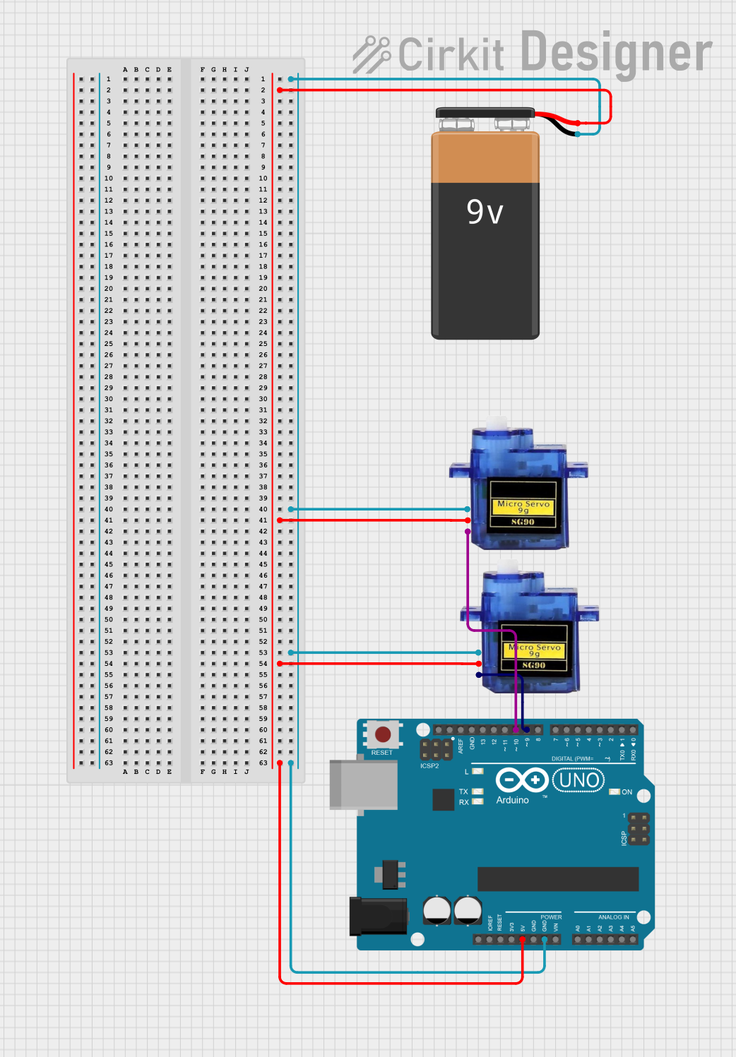
Circuit Documentation
Summary of the Circuit
This circuit is designed to control two micro servo motors using an Arduino UNO microcontroller. The servos are powered by a 9V battery and are controlled by the PWM (Pulse Width Modulation) signals from the Arduino UNO. The circuit allows for the independent movement of each servo motor through a range of 0 to 180 degrees.
Component List
Arduino UNO
- Description: A microcontroller board based on the ATmega328P.
- Purpose: Acts as the central controller for the servo motors, generating PWM signals to control their position.
Micro servo 9G (x2)
- Description: A small and lightweight servo motor suitable for projects that require simple motion.
- Purpose: Receives PWM signals from the Arduino UNO to adjust the angle of the servo arm.
9V Battery
- Description: A standard 9V battery used to provide power to the circuit.
- Purpose: Supplies power to the Arduino UNO and the servo motors.
Wiring Details
Arduino UNO
- 5V: Connected to the +5V pins of both micro servo motors and the + terminal of the 9V battery.
- GND: Connected to the GND pins of both micro servo motors and the - terminal of the 9V battery.
- D9: Connected to the PWM pin of one micro servo motor.
- D10: Connected to the PWM pin of the other micro servo motor.
Micro servo 9G (Servo 1)
- GND: Connected to the GND of the Arduino UNO and the - terminal of the 9V battery.
- +5V: Connected to the 5V of the Arduino UNO and the + terminal of the 9V battery.
- PWM: Connected to the D10 pin of the Arduino UNO.
Micro servo 9G (Servo 2)
- GND: Connected to the GND of the Arduino UNO and the - terminal of the 9V battery.
- +5V: Connected to the 5V of the Arduino UNO and the + terminal of the 9V battery.
- PWM: Connected to the D9 pin of the Arduino UNO.
9V Battery
- -: Connected to the GND of the Arduino UNO and the GND pins of both micro servo motors.
- +: Connected to the 5V of the Arduino UNO and the +5V pins of both micro servo motors.
Documented Code
#include <Servo.h>

Servo servo1; // Bottom servo motor
Servo servo2; // Top servo motor

void setup() {
  servo1.attach(9);  // Attach bottom servo to pin 9
  servo2.attach(10); // Attach top servo to pin 10
  servo1.write(0);
  servo2.write(0);
}

void loop() {
  // Move bottom servo from 0 to 180 degrees and back
  for (int pos = 0; pos <= 180; pos += 1) {
    servo1.write(pos);
    delay(10);
  }
  for (int pos = 180; pos >= 0; pos -= 1) {
    servo1.write(pos);
    delay(10);
  }

  // Move top servo from 0 to 180 degrees and back
  for (int pos = 0; pos <= 180; pos += 1) {
    servo2.write(pos);
    delay(10);
  }
  for (int pos = 180; pos >= 0; pos -= 1) {
    servo2.write(pos);
    delay(10);
  }
}
Filename: sketch.ino
Description: This Arduino sketch initializes two servo objects and attaches them to pins 9 and 10, respectively. In the loop function, it moves each servo from 0 to 180 degrees and then back to 0 degrees in a continuous loop. The movement is achieved by incrementing the position degree by degree with a short delay between each increment to create a smooth motion.