ESP32-Controlled Multiplexed AC Lighting System
Circuit Documentation
Summary
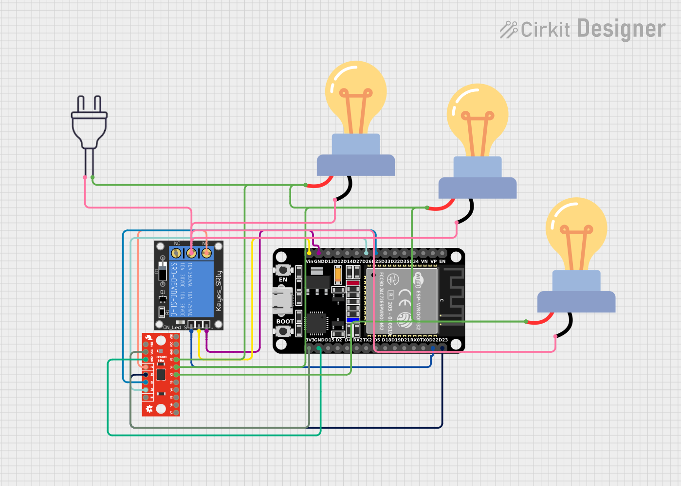
This circuit is designed to control three AC-powered LED bulbs using an ESP32 microcontroller and a 1-channel relay module. The ESP32 is also interfaced with a SparkFun 74HC4051 8-Channel Multiplexer (Mux) to select which LED bulb to power. The relay module acts as an electronic switch that is controlled by the ESP32 to turn the bulbs on or off. The power for the bulbs is supplied by a 220V AC power source.
Component List
ESP32 (30 pin)
- Description: A microcontroller with Wi-Fi and Bluetooth capabilities.
- Pins: EN, VP, VN, D34, D35, D32, D33, D25, D26, D27, D14, D12, D13, GND, Vin, D23, D22, TX0, RX0, D21, D19, D18, D5, TX2, RX2, D4, D2, D15, 3V3
1-Channel Relay (5V 10A)
- Description: An electromechanical switch that allows the ESP32 to control high-power devices.
- Pins: NC, signal, C, power, NO, ground
Power 220V
- Description: The main AC power source for the circuit.
- Pins: hot wire, neutral wire
LED bulb AC / Bombillo AC
- Description: An AC-powered LED light bulb.
- Pins: +, -
SparkFun 74HC4051 8-Channel Mux Breakout
- Description: A multiplexer that allows the ESP32 to select between multiple inputs or outputs.
- Pins: Y7, Y6, Y5, Y4, Y3, Y2, Y1, Y0, GND, VCC, VEE, !E!, S2, S1, S0, Z
Wiring Details
ESP32 (30 pin)
- D25 connected to SparkFun 74HC4051 S1
- D26 connected to SparkFun 74HC4051 S2
- GND connected to 1-Channel Relay ground and SparkFun 74HC4051 GND
- Vin connected to 1-Channel Relay power
- D23 connected to SparkFun 74HC4051 S0
- D22 connected to 1-Channel Relay signal
- 3V3 connected to SparkFun 74HC4051 VCC
1-Channel Relay (5V 10A)
- ground connected to ESP32 GND
- power connected to ESP32 Vin
- signal connected to ESP32 D22
- C connected to Power 220V hot wire and LED bulbs AC -
- NO connected to SparkFun 74HC4051 Z
Power 220V
- hot wire connected to 1-Channel Relay C
- neutral wire connected to SparkFun 74HC4051 Y2, Y1, Y0, and LED bulbs AC +
LED bulb AC / Bombillo AC
- connected to Power 220V neutral wire
- connected to 1-Channel Relay C
SparkFun 74HC4051 8-Channel Mux Breakout
- S1 connected to ESP32 D25
- S2 connected to ESP32 D26
- GND connected to ESP32 GND
- VCC connected to ESP32 3V3
- S0 connected to ESP32 D23
- Z connected to 1-Channel Relay NO
- Y2, Y1, Y0 connected to Power 220V neutral wire
Documented Code
// sketch.ino
const int relayPin = 22; // Relay control pin
const int muxS0 = 23; // Multiplexer control pin S0
const int muxS1 = 25; // Multiplexer control pin S1
const int muxS2 = 26; // Multiplexer control pin S2

void setup() {
  pinMode(relayPin, OUTPUT);
  pinMode(muxS0, OUTPUT);
  pinMode(muxS1, OUTPUT);
  pinMode(muxS2, OUTPUT);
  digitalWrite(relayPin, LOW); // Ensure relay is off initially
}

void loop() {
  // Control the first bulb
  selectMuxChannel(0);
  digitalWrite(relayPin, HIGH);
  delay(1000); // Keep the relay on for 1 second
  digitalWrite(relayPin, LOW);
  delay(1000); // Wait before switching to the next bulb

  // Control the second bulb
  selectMuxChannel(1);
  digitalWrite(relayPin, HIGH);
  delay(1000);
  digitalWrite(relayPin, LOW);
  delay(1000);

  // Control the third bulb
  selectMuxChannel(2);
  digitalWrite(relayPin, HIGH);
  delay(1000);
  digitalWrite(relayPin, LOW);
  delay(1000);
}

void selectMuxChannel(int channel) {
  digitalWrite(muxS0, channel & 0x01);
  digitalWrite(muxS1, (channel >> 1) & 0x01);
  digitalWrite(muxS2, (channel >> 2) & 0x01);
}
This code configures the ESP32 to control a relay and select channels on a multiplexer. The relay is used to switch the power to the LED bulbs, and the multiplexer selects which bulb to power. The selectMuxChannel function sets the appropriate control pins to select the desired channel on the multiplexer. The loop function cycles through the bulbs, turning each on for one second before moving to the next.