Arduino-Based Solar and Grid Power Management System with Battery Backup
Circuit Documentation
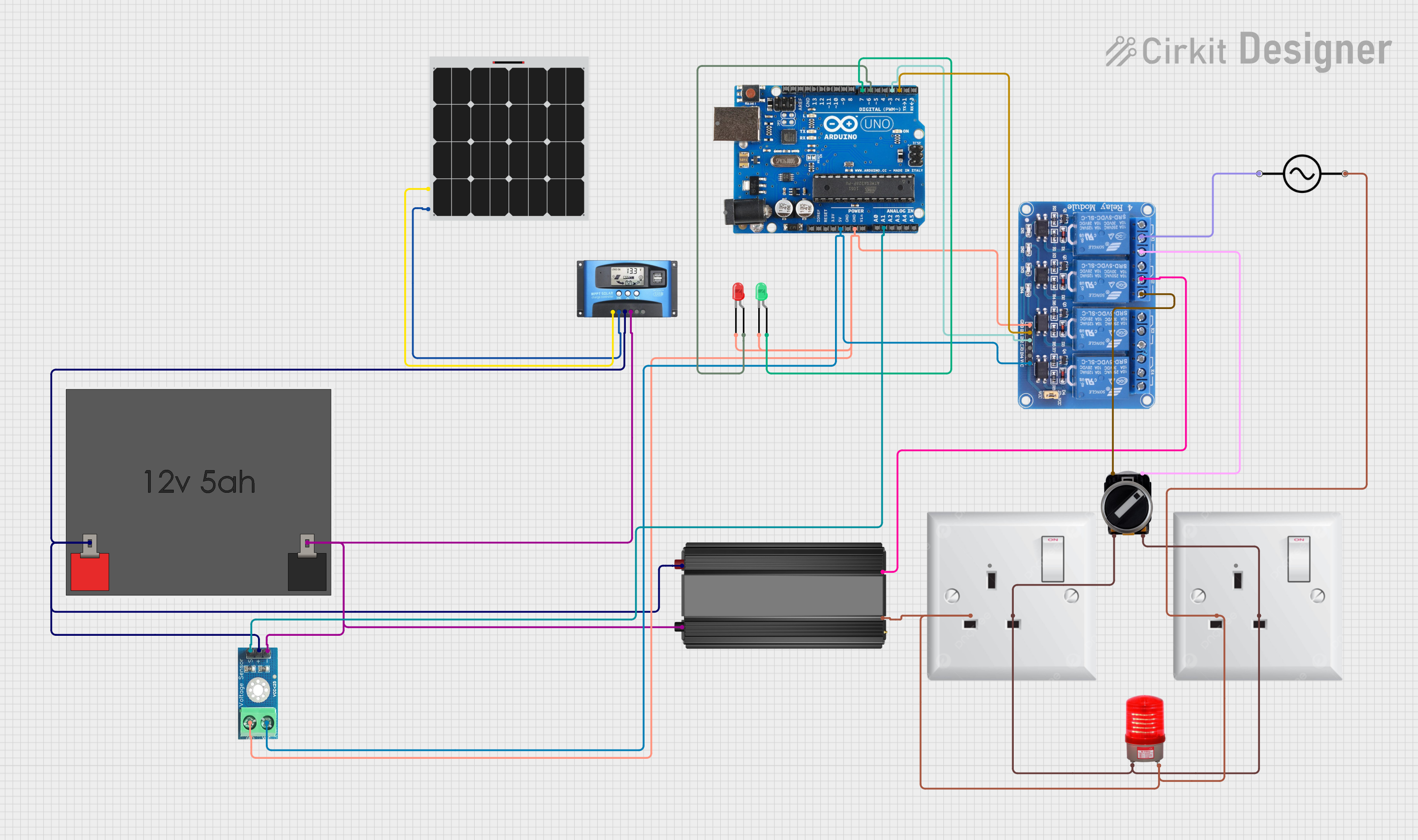
Summary
This circuit is designed to manage power from a solar panel and a 12V battery, with an MPPT (Maximum Power Point Tracking) Solar Charge Controller (SCC) to optimize the charging process. The circuit also includes a power inverter to convert DC to AC, a relay module to switch between power sources, and an Arduino Uno R3 microcontroller to control the relays and LEDs indicating the power source status. Additionally, a voltage sensor is used to monitor the battery voltage, and a 3-position switch allows manual selection between power sources.
Component List
Power Inverter
- Description: Converts DC power to AC power.
- Pins: +, -
12V 5Ah Battery
- Description: Provides 12V DC power.
- Pins: 12v +, 12v -
Solar Panel
- Description: Generates DC power from sunlight.
- Pins: +, -
MPPT SCC
- Description: Optimizes the charging of the battery from the solar panel.
- Pins: SOLAR+, SOLAR-, BATTERY+, BATTERY-, LOAD+, LOAD-
Relay 4 Channel 5V
- Description: Switches between different power sources.
- Pins: GND, IN1, IN2, IN3, IN4, VCC, COM1, COM2, COM3, COM4, NO1, NO2, NO3, NO4, NC1, NC2, NC3, NC4
Arduino Uno R3
- Description: Microcontroller for controlling relays and LEDs.
- Pins: D8, D9, D10, D11, D12, D13, GND, AREF, SDA, SCL, D0/RX, D1/Tx, D2, D3, D4, D5, 6, D7, A5/SCL, A4/SDA, A3, A2, A1, A0, Vin, 5V, 3.3V, RESET, IOREF, NONE, USB Jack, Power Jack
LED: Two Pin (Green)
- Description: Indicates the status of the solar power source.
- Pins: cathode, anode
LED: Two Pin (Red)
- Description: Indicates the status of the grid power source.
- Pins: cathode, anode
Voltage Sensor DC 25V
- Description: Monitors the voltage of the battery.
- Pins: +, -, output, gnd, vcc
AC Wall Plug Point
- Description: Provides AC power from the wall outlet.
- Pins: E, N, L
Red Light 220VAC
- Description: Indicates the status of the AC power.
- Pins: +, -
Alternative Current (AC)
- Description: Represents the AC power source.
- Pins: Line, Neutral
3 Position Switch
- Description: Allows manual selection between power sources.
- Pins: 23, 11, 24, 12
Wiring Details
Power Inverter
Pin - connected to:
- Voltage Sensor DC 25V (-)
- MPPT SCC (BATTERY-)
- 12V 5Ah Battery (12v -)
- AC Wall Plug Point (N)
- Alternative Current (AC) (Neutral)
- Red Light 220VAC (-)
Pin + connected to:
- Voltage Sensor DC 25V (+)
- MPPT SCC (BATTERY+)
- 12V 5Ah Battery (12v +)
- Relay 4 Channel 5V (COM2)
12V 5Ah Battery
Pin 12v + connected to:
- Power Inverter (+)
- Voltage Sensor DC 25V (+)
- MPPT SCC (BATTERY+)
Pin 12v - connected to:
- Power Inverter (-)
- Voltage Sensor DC 25V (-)
- MPPT SCC (BATTERY-)
Solar Panel
Pin + connected to:
- MPPT SCC (SOLAR+)
Pin - connected to:
- MPPT SCC (SOLAR-)
MPPT SCC
Pin SOLAR+ connected to:
- Solar Panel (+)
Pin SOLAR- connected to:
- Solar Panel (-)
Pin BATTERY+ connected to:
- Power Inverter (+)
- Voltage Sensor DC 25V (+)
- 12V 5Ah Battery (12v +)
Pin BATTERY- connected to:
- Power Inverter (-)
- Voltage Sensor DC 25V (-)
- 12V 5Ah Battery (12v -)
Relay 4 Channel 5V
Pin GND connected to:
- Arduino Uno R3 (GND)
- Voltage Sensor DC 25V (gnd)
- LED: Two Pin (Green) (cathode)
- LED: Two Pin (Red) (cathode)
Pin IN1 connected to:
- Arduino Uno R3 (D2)
Pin IN2 connected to:
- Arduino Uno R3 (D3)
Pin VCC connected to:
- Arduino Uno R3 (5V)
- Voltage Sensor DC 25V (vcc)
Pin COM1 connected to:
- Alternative Current (AC) (Line)
Pin NO1 connected to:
- 3 Position Switch (11)
Pin NO2 connected to:
- 3 Position Switch (23)
Pin COM2 connected to:
- Power Inverter (+)
Arduino Uno R3
Pin GND connected to:
- Relay 4 Channel 5V (GND)
- Voltage Sensor DC 25V (gnd)
- LED: Two Pin (Green) (cathode)
- LED: Two Pin (Red) (cathode)
Pin D2 connected to:
- Relay 4 Channel 5V (IN1)
Pin D3 connected to:
- Relay 4 Channel 5V (IN2)
Pin 5V connected to:
- Relay 4 Channel 5V (VCC)
- Voltage Sensor DC 25V (vcc)
Pin 6 connected to:
- LED: Two Pin (Red) (anode)
Pin D7 connected to:
- LED: Two Pin (Green) (anode)
Pin A1 connected to:
- Voltage Sensor DC 25V (output)
LED: Two Pin (Green)
Pin cathode connected to:
- Arduino Uno R3 (GND)
- Relay 4 Channel 5V (GND)
- Voltage Sensor DC 25V (gnd)
Pin anode connected to:
- Arduino Uno R3 (D7)
LED: Two Pin (Red)
Pin cathode connected to:
- Arduino Uno R3 (GND)
- Relay 4 Channel 5V (GND)
- Voltage Sensor DC 25V (gnd)
Pin anode connected to:
- Arduino Uno R3 (6)
Voltage Sensor DC 25V
Pin + connected to:
- Power Inverter (+)
- MPPT SCC (BATTERY+)
- 12V 5Ah Battery (12v +)
Pin - connected to:
- Power Inverter (-)
- MPPT SCC (BATTERY-)
- 12V 5Ah Battery (12v -)
Pin output connected to:
- Arduino Uno R3 (A1)
Pin gnd connected to:
- Arduino Uno R3 (GND)
- Relay 4 Channel 5V (GND)
- LED: Two Pin (Green) (cathode)
- LED: Two Pin (Red) (cathode)
Pin vcc connected to:
- Arduino Uno R3 (5V)
- Relay 4 Channel 5V (VCC)
AC Wall Plug Point
Pin N connected to:
- Power Inverter (-)
- Alternative Current (AC) (Neutral)
- Red Light 220VAC (-)
Pin L connected to:
- 3 Position Switch (24)
- 3 Position Switch (12)
- Red Light 220VAC (+)
Red Light 220VAC
Pin - connected to:
- Power Inverter (-)
- AC Wall Plug Point (N)
- Alternative Current (AC) (Neutral)
Pin + connected to:
- AC Wall Plug Point (L)
- 3 Position Switch (24)
- 3 Position Switch (12)
Alternative Current (AC)
- **Pin Line