Arduino UNO-Based Smart Home Security System with IR Sensor and Keypad
Circuit Documentation
Summary
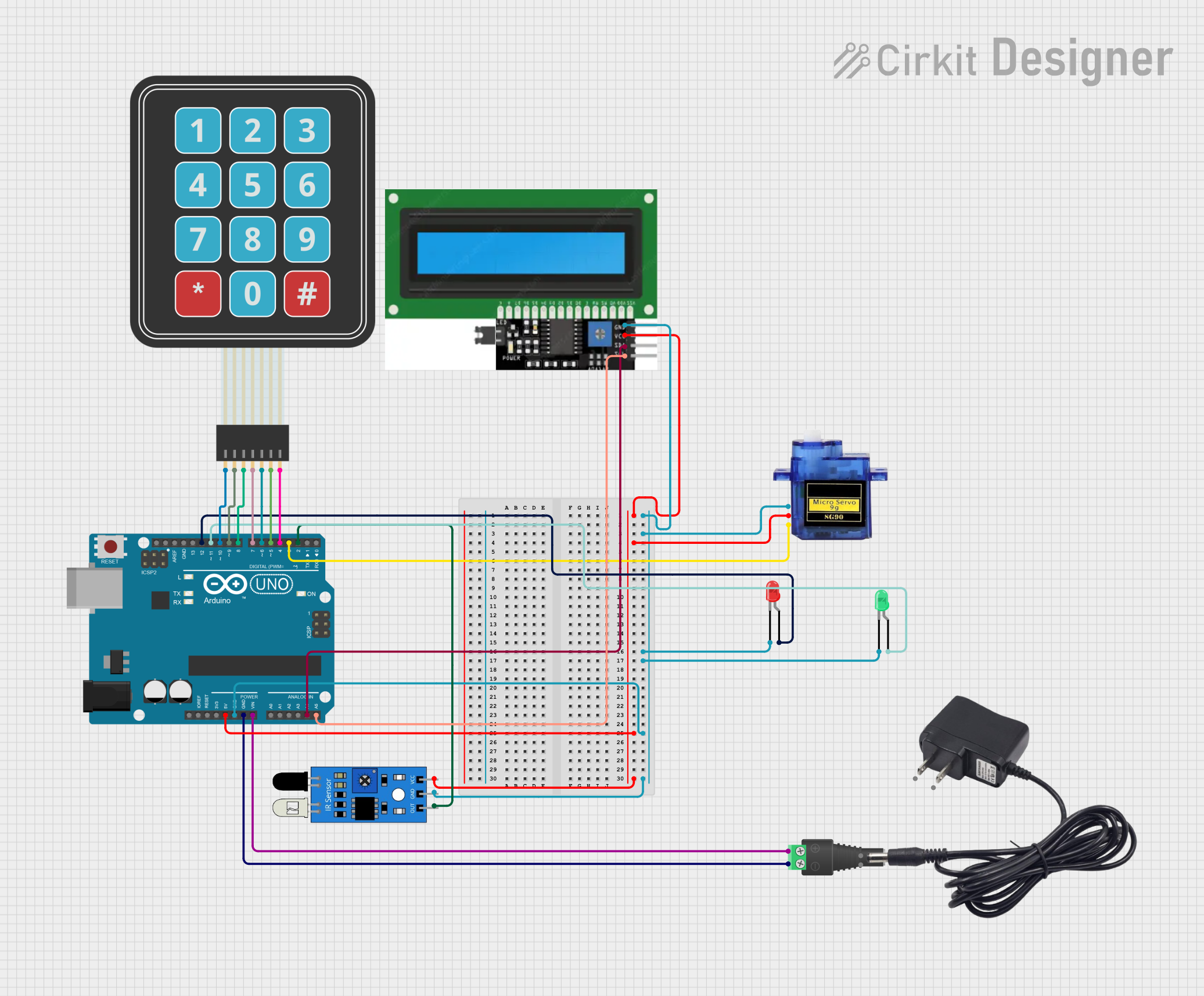
This circuit involves an Arduino UNO microcontroller interfacing with various components including LEDs, an IR sensor, a micro servo, an I2C display, and a membrane matrix keypad. The circuit is powered through a 2.1mm barrel jack with a terminal block. The Arduino UNO is programmed to control these components based on the input from the IR sensor and keypad.
Component List
Arduino UNO
- Description: A microcontroller board based on the ATmega328P.
- Pins: UNUSED, IOREF, Reset, 3.3V, 5V, GND, Vin, A0, A1, A2, A3, A4, A5, SCL, SDA, AREF, D13, D12, D11, D10, D9, D8, D7, D6, D5, D4, D3, D2, D1, D0
LED: Two Pin (red)
- Description: A red LED with two pins.
- Pins: cathode, anode
2.1mm Barrel Jack with Terminal Block
- Description: A barrel jack for power input with terminal block connections.
- Pins: POS, NEG
IR Sensor
- Description: An infrared sensor for detecting objects.
- Pins: out, gnd, vcc
LED: Two Pin (green)
- Description: A green LED with two pins.
- Pins: cathode, anode
Micro Servo 9G
- Description: A small servo motor for precise control.
- Pins: GND, +5V, PWM
12V Adapter
- Description: A 12V power adapter.
- Pins: VCC, GND
I2C Display
- Description: A display module with I2C interface.
- Pins: GND, VCC, SDL, SCL
Membrane Matrix Keypad
- Description: A keypad with a matrix of buttons.
- Pins: Row 1, Row 2, Row 3, Row 4, Column 1, Column 2, Column 3
Wiring Details
Arduino UNO
- 5V: Connected to VCC of I2C Display, +5V of Micro Servo, and vcc of IR Sensor.
- GND: Connected to GND of I2C Display, GND of Micro Servo, cathode of Red LED, cathode of Green LED, and gnd of IR Sensor.
- Vin: Connected to POS of 2.1mm Barrel Jack.
- A4: Connected to SDL of I2C Display.
- A5: Connected to SCL of I2C Display.
- D12: Connected to anode of Red LED.
- D11: Connected to anode of Green LED.
- D10: Connected to Row 1 of Membrane Matrix Keypad.
- D9: Connected to Row 2 of Membrane Matrix Keypad.
- D8: Connected to Row 3 of Membrane Matrix Keypad.
- D7: Connected to Row 4 of Membrane Matrix Keypad.
- D6: Connected to Column 1 of Membrane Matrix Keypad.
- D5: Connected to Column 2 of Membrane Matrix Keypad.
- D4: Connected to Column 3 of Membrane Matrix Keypad.
- D3: Connected to PWM of Micro Servo.
- D2: Connected to out of IR Sensor.
LED: Two Pin (red)
- cathode: Connected to GND of Arduino UNO.
- anode: Connected to D12 of Arduino UNO.
LED: Two Pin (green)
- cathode: Connected to GND of Arduino UNO.
- anode: Connected to D11 of Arduino UNO.
2.1mm Barrel Jack with Terminal Block
- POS: Connected to Vin of Arduino UNO.
- NEG: Connected to GND of Arduino UNO.
IR Sensor
- out: Connected to D2 of Arduino UNO.
- gnd: Connected to GND of Arduino UNO.
- vcc: Connected to 5V of Arduino UNO.
Micro Servo 9G
- GND: Connected to GND of Arduino UNO.
- +5V: Connected to 5V of Arduino UNO.
- PWM: Connected to D3 of Arduino UNO.
I2C Display
- GND: Connected to GND of Arduino UNO.
- VCC: Connected to 5V of Arduino UNO.
- SDL: Connected to A4 of Arduino UNO.
- SCL: Connected to A5 of Arduino UNO.
Membrane Matrix Keypad
- Row 1: Connected to D10 of Arduino UNO.
- Row 2: Connected to D9 of Arduino UNO.
- Row 3: Connected to D8 of Arduino UNO.
- Row 4: Connected to D7 of Arduino UNO.
- Column 1: Connected to D6 of Arduino UNO.
- Column 2: Connected to D5 of Arduino UNO.
- Column 3: Connected to D4 of Arduino UNO.
Code Documentation
Arduino UNO Code
void setup() {
  // put your setup code here, to run once:

}

void loop() {
  // put your main code here, to run repeatedly:

}
This code is a basic template for the Arduino UNO. The setup() function is where you initialize your components and settings, and the loop() function is where the main logic of your program runs repeatedly. You can add your specific logic to control the LEDs, read from the IR sensor, operate the servo, and interact with the keypad and display in these functions.