
Arduino UNO-Based Smart Home Control System with LCD Display and GSM Module
View and Edit Project In Cirkit Designer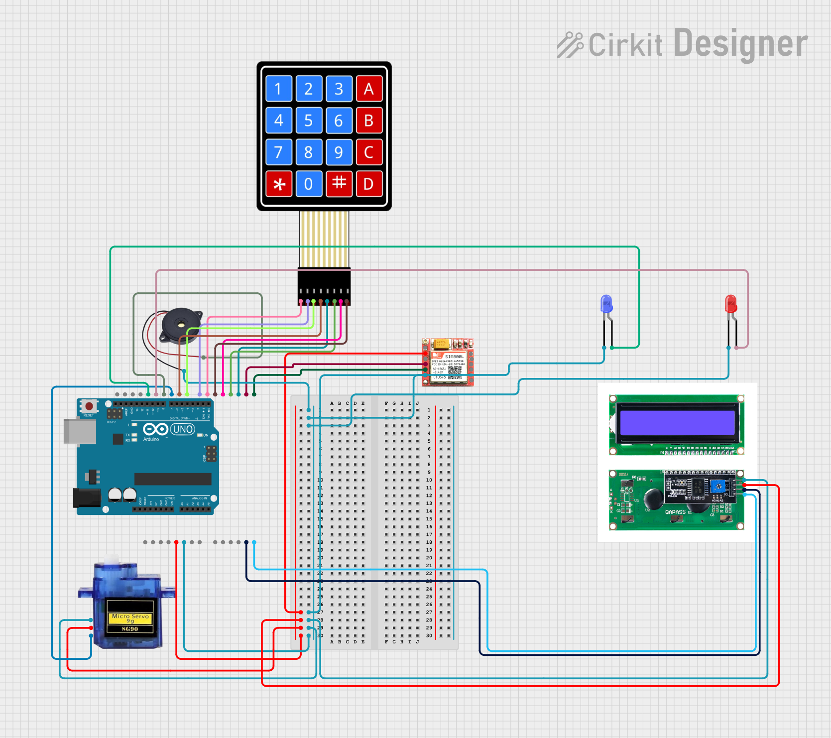
Circuit Documentation
Summary
This document provides a detailed overview of a circuit that includes an Arduino UNO microcontroller, an LCD with I2C interface, a micro servo, a SIM800L GSM module, a buzzer, two LEDs (blue and red), and a 4x4 membrane matrix keypad. The circuit is designed to interface these components with the Arduino UNO, allowing for various functionalities such as display, motor control, GSM communication, sound output, and user input via the keypad.
Component List
Arduino UNO
- Description: A microcontroller board based on the ATmega328P.
- Pins: UNUSED, IOREF, Reset, 3.3V, 5V, GND, Vin, A0, A1, A2, A3, A4, A5, SCL, SDA, AREF, D13, D12, D11, D10, D9, D8, D7, D6, D5, D4, D3, D2, D1, D0
LCD with I2C Interface (lcdi2c)
- Description: An LCD display module with I2C interface.
- Pins: GND, VCC, SDA, SCL
Micro Servo 9G
- Description: A small servo motor used for precise control of angular position.
- Pins: GND, +5V, PWM
SIM800L GSM Module
- Description: A GSM module for communication over cellular networks.
- Pins: NFT, RING, VCC, DTR, RST, MIC +, RXD, MIC-, TXD, SPK+, GND, SPK-
Buzzer
- Description: A simple sound-producing device.
- Pins: GND, IN
LED: Two Pin (Blue)
- Description: A blue LED.
- Pins: cathode, anode
LED: Two Pin (Red)
- Description: A red LED.
- Pins: cathode, anode
4x4 Membrane Matrix Keypad
- Description: A keypad with 4 rows and 4 columns.
- Pins: R1, R2, R3, R4, C1, C2, C3, C4
Wiring Details
Arduino UNO
- GND: Connected to GND of Buzzer, Blue LED, Red LED, SIM800L, LCD with I2C, Micro Servo
- 5V: Connected to VCC of SIM800L, LCD with I2C, +5V of Micro Servo
- A4: Connected to SDA of LCD with I2C
- A5: Connected to SCL of LCD with I2C
- D13: Connected to anode of Blue LED
- D12: Connected to anode of Red LED
- D11: Connected to IN of Buzzer
- D10: Connected to PWM of Micro Servo
- D9: Connected to R4 of 4x4 Membrane Matrix Keypad
- D8: Connected to R3 of 4x4 Membrane Matrix Keypad
- D7: Connected to R2 of 4x4 Membrane Matrix Keypad
- D6: Connected to R1 of 4x4 Membrane Matrix Keypad
- D5: Connected to C4 of 4x4 Membrane Matrix Keypad
- D4: Connected to C3 of 4x4 Membrane Matrix Keypad
- D3: Connected to C2 of 4x4 Membrane Matrix Keypad
- D2: Connected to C1 of 4x4 Membrane Matrix Keypad
- D1: Connected to RXD of SIM800L
- D0: Connected to TXD of SIM800L
LCD with I2C Interface
- GND: Connected to GND of Arduino UNO
- VCC: Connected to 5V of Arduino UNO
- SDA: Connected to A4 of Arduino UNO
- SCL: Connected to A5 of Arduino UNO
Micro Servo 9G
- GND: Connected to GND of Arduino UNO
- +5V: Connected to 5V of Arduino UNO
- PWM: Connected to D10 of Arduino UNO
SIM800L GSM Module
- GND: Connected to GND of Arduino UNO
- VCC: Connected to 5V of Arduino UNO
- RXD: Connected to D1 of Arduino UNO
- TXD: Connected to D0 of Arduino UNO
Buzzer
- GND: Connected to GND of Arduino UNO
- IN: Connected to D11 of Arduino UNO
LED: Two Pin (Blue)
- cathode: Connected to GND of Arduino UNO
- anode: Connected to D13 of Arduino UNO
LED: Two Pin (Red)
- cathode: Connected to GND of Arduino UNO
- anode: Connected to D12 of Arduino UNO
4x4 Membrane Matrix Keypad
- R1: Connected to D6 of Arduino UNO
- R2: Connected to D7 of Arduino UNO
- R3: Connected to D8 of Arduino UNO
- R4: Connected to D9 of Arduino UNO
- C1: Connected to D2 of Arduino UNO
- C2: Connected to D3 of Arduino UNO
- C3: Connected to D4 of Arduino UNO
- C4: Connected to D5 of Arduino UNO
Documented Code
Arduino UNO Code (sketch.ino)
void setup() {
  // put your setup code here, to run once:

}

void loop() {
  // put your main code here, to run repeatedly:

}
Additional Documentation (documentation.txt)
This document provides a comprehensive overview of the circuit, including the components used, their connections, and the code running on the Arduino UNO.