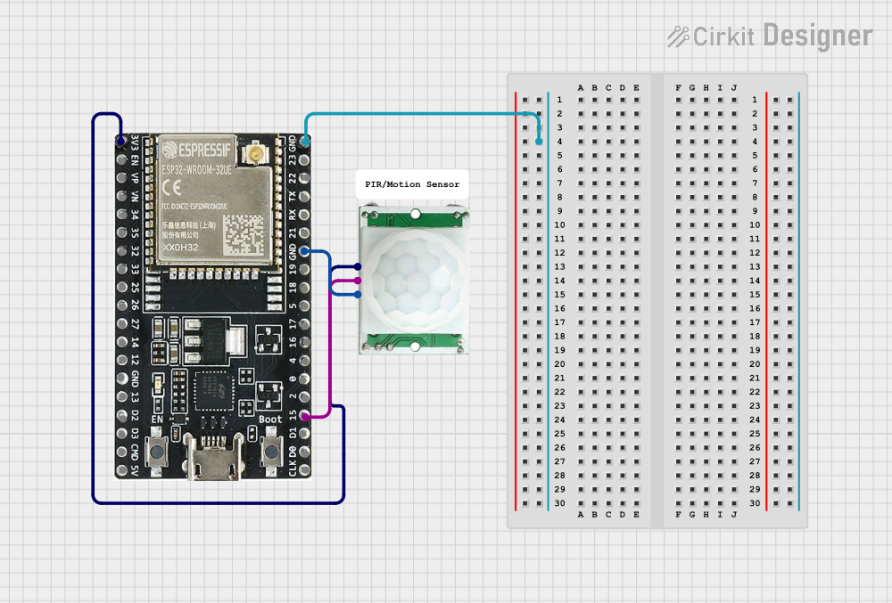
ESP32-Based Motion Detection System

Circuit Documentation
Summary of the Circuit
This circuit integrates a PIR (Passive Infrared) motion sensor with an ESP32-WROOM-32UE microcontroller. The PIR sensor is used to detect motion through changes in infrared levels, and its output is fed into the ESP32 for processing. The ESP32 can then take appropriate actions based on the presence or absence of motion, such as sending alerts or triggering other devices. The circuit is powered by the ESP32's 3.3V output, ensuring that the PIR sensor operates within its required voltage range.
Component List
PIR/Motion Sensor
- Description: A sensor that detects motion by measuring changes in the infrared light.
- Pins: GND, OUTPUT, VCC
ESP32-WROOM-32UE
- Description: A powerful microcontroller with Wi-Fi and Bluetooth capabilities, suitable for a wide range of IoT applications.
- Pins: 3v3, EN, VP, VN, 34, 35, 32, 33, 25, 26, 27, 14, 12, GND, 13, D2, D3, 5V, 23, 22, TX, RX, 21, 19, 18, 5, 17, 16, 4, 0, 2, 15, D1, D0, CKL
Comment
- Description: This appears to be a placeholder or annotation and does not represent a physical component in the circuit.
Wiring Details
PIR/Motion Sensor
- GND: Connected to the GND pin of the ESP32-WROOM-32UE.
- OUTPUT: Connected to pin 15 of the ESP32-WROOM-32UE.
- VCC: Connected to the 3v3 pin of the ESP32-WROOM-32UE.
ESP32-WROOM-32UE
- GND: Shared ground with the PIR/Motion Sensor.
- 3v3: Provides power to the PIR/Motion Sensor.
- 15: Receives the OUTPUT signal from the PIR/Motion Sensor.
Documented Code
No code has been provided for the microcontroller. To fully utilize the ESP32-WROOM-32UE with the PIR sensor, embedded code is required to initialize the microcontroller's GPIO pins, set up Wi-Fi or Bluetooth communication if needed, and handle the logic for motion detection events. The code would typically include interrupt service routines or polling loops to read the state of the PIR sensor's output pin and then take action when motion is detected.