
Arduino Mega 2560 and L298N Motor Driver Controlled Dual DC Motor System
View and Edit Project In Cirkit Designer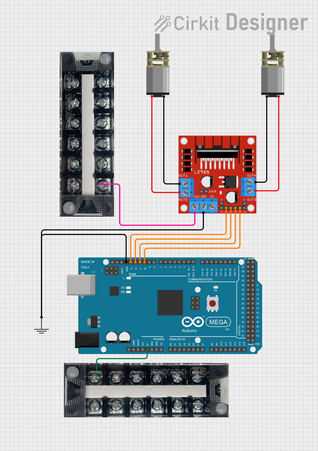
Circuit Documentation
Summary
This circuit is designed to control two DC Mini Metal Gear Motors using an L298N DC motor driver, which is interfaced with an Arduino Mega 2560. The circuit includes power connections and ground connections to ensure proper operation.
Component List
L298N DC Motor Driver
- Description: A dual H-Bridge motor driver that allows control of the speed and direction of two DC motors.
- Pins: OUT1, OUT2, 12V, GND, 5V, OUT3, OUT4, 5V-ENA-JMP-I, 5V-ENA-JMP-O, +5V-J1, +5V-J2, ENA, IN1, IN2, IN3, IN4, ENB
DC Mini Metal Gear Motor (Motor 1)
- Description: A small DC motor with metal gears for increased torque.
- Pins: IN1, IN2
DC Mini Metal Gear Motor (Motor 2)
- Description: A small DC motor with metal gears for increased torque.
- Pins: IN1, IN2
Arduino Mega 2560
- Description: A microcontroller board based on the ATmega2560, featuring numerous I/O pins and PWM capabilities.
- Pins: IOREF, RESET, 3V3, 5V, GND, VIN, A0-A15, D21/SCL, D20/SDA, D19/RX1, D18/TX1, D17 PWM/RX2, D16 PWM/TX2, D15/RX3, D14/TX3, D0 RX0, D1 TX0, D2-D13 PWM, AREF, SDA, SCL, D22-D53
GND
- Description: Ground connection for the circuit.
- Pins: GND
Terminal Block KTB1 20A 6P (Block 1)
- Description: A terminal block for connecting power and other signals.
- Pins: 1, 2, 3, 4, 5, 6
Terminal Block KTB1 20A 6P (Block 2)
- Description: A terminal block for connecting power and other signals.
- Pins: 1, 2, 3, 4, 5, 6
Wiring Details
L298N DC Motor Driver
- OUT1 connected to IN2 of DC Mini Metal Gear Motor (Motor 2)
- OUT2 connected to IN1 of DC Mini Metal Gear Motor (Motor 2)
- 12V connected to Pin 6 of Terminal Block KTB1 20A 6P (Block 2)
- GND connected to GND of GND and GND of Arduino Mega 2560
- OUT3 connected to IN2 of DC Mini Metal Gear Motor (Motor 1)
- OUT4 connected to IN1 of DC Mini Metal Gear Motor (Motor 1)
- IN1 connected to D13 PWM of Arduino Mega 2560
- IN2 connected to D12 PWM of Arduino Mega 2560
- IN3 connected to D11 PWM of Arduino Mega 2560
- IN4 connected to D10 PWM of Arduino Mega 2560
DC Mini Metal Gear Motor (Motor 1)
- IN1 connected to OUT4 of L298N DC Motor Driver
- IN2 connected to OUT3 of L298N DC Motor Driver
DC Mini Metal Gear Motor (Motor 2)
- IN1 connected to OUT2 of L298N DC Motor Driver
- IN2 connected to OUT1 of L298N DC Motor Driver
Arduino Mega 2560
- GND connected to GND of GND and GND of L298N DC Motor Driver
- 5V connected to Pin 6 of Terminal Block KTB1 20A 6P (Block 1)
- D13 PWM connected to IN1 of L298N DC Motor Driver
- D12 PWM connected to IN2 of L298N DC Motor Driver
- D11 PWM connected to IN3 of L298N DC Motor Driver
- D10 PWM connected to IN4 of L298N DC Motor Driver
GND
- GND connected to GND of L298N DC Motor Driver and GND of Arduino Mega 2560
Terminal Block KTB1 20A 6P (Block 1)
- Pin 6 connected to 5V of Arduino Mega 2560
Terminal Block KTB1 20A 6P (Block 2)
- Pin 6 connected to 12V of L298N DC Motor Driver
Documented Code
Arduino Mega 2560 Code
void setup() {
  // put your setup code here, to run once:

}

void loop() {
  // put your main code here, to run repeatedly:

}
This code is a basic template for the Arduino Mega 2560. The setup() function is where you initialize your settings, and the loop() function is where the main code runs repeatedly. You can add motor control logic in these functions to control the DC motors via the L298N motor driver.