
ESP32-Based Voltage and Current Monitoring System with Wi-Fi Connectivity
View and Edit Project In Cirkit Designer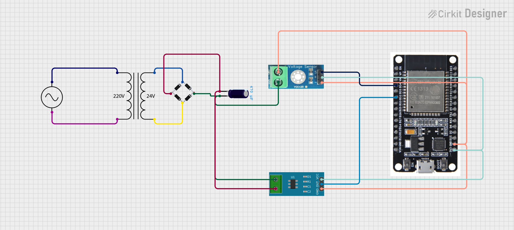
Circuit Documentation
Summary
This circuit is designed to measure voltage and current using a voltage sensor and a current sensor, interfaced with an ESP32 microcontroller. The circuit also includes a power supply system that converts AC to DC using a power transformer and a bridge rectifier. The measured values are processed and displayed by the ESP32.
Component List
Voltage Sensor DC 25V
- Pins: +, -, output, gnd, vcc
- Description: Measures DC voltage up to 25V.
- Purpose: To measure the voltage in the circuit.
Current Sensor 5A
- Pins: 1, 2, GND, OUT, VCC
- Description: Measures current up to 5A.
- Purpose: To measure the current in the circuit.
Bridge Rectifier
- Pins: Source_in-, source_out-, source_out+, source_in+
- Description: Converts AC to DC.
- Purpose: To rectify the AC voltage from the transformer to DC.
Power Transformer (220V to 24V)
- Pins: 2 - Primary, 1 - Primary, 3 - Secondary, 4 - Secondary
- Description: Steps down 220V AC to 24V AC.
- Purpose: To step down the high voltage AC to a lower voltage suitable for rectification.
ESP32
- Pins: EN, VP, VN, D34, D35, D32, D33, D25, D26, D27, D14, D12, D13, GND, VIN, 3V3, D15, D2, D4, RX2, TX2, D5, D18, D19, D21, RX0, TX0, D22, D23, BOOT
- Description: A microcontroller with Wi-Fi and Bluetooth capabilities.
- Purpose: To process and display the voltage and current measurements.
Electrolytic Capacitor
- Pins: -, +
- Description: 0.00047 Farads
- Purpose: To filter the rectified DC voltage.
AC Supply
- Pins: +ve, -ve
- Description: Provides AC voltage.
- Purpose: To supply AC voltage to the transformer.
Wiring Details
Voltage Sensor DC 25V
- output connected to ESP32 D34
- + connected to Current Sensor 5A VCC and ESP32 3V3
- - connected to Voltage Sensor DC 25V gnd, Current Sensor 5A GND, and ESP32 GND
- vcc connected to Bridge Rectifier source_out+, Current Sensor 5A 1, and Electrolytic Capacitor +
Current Sensor 5A
- OUT connected to ESP32 D32
- GND connected to Voltage Sensor DC 25V -, Voltage Sensor DC 25V gnd, and ESP32 GND
- VCC connected to Voltage Sensor DC 25V + and ESP32 3V3
- 1 connected to Voltage Sensor DC 25V vcc, Bridge Rectifier source_out+, and Electrolytic Capacitor +
- 2 connected to Bridge Rectifier source_out- and Electrolytic Capacitor -
Bridge Rectifier
- source_out+ connected to Voltage Sensor DC 25V vcc, Current Sensor 5A 1, and Electrolytic Capacitor +
- source_out- connected to Current Sensor 5A 2 and Electrolytic Capacitor -
- Source_in- connected to Power Transformer (220V to 24V) 3 - Secondary
- source_in+ connected to Power Transformer (220V to 24V) 4 - Secondary
Power Transformer (220V to 24V)
- 2 - Primary connected to AC Supply -ve
- 1 - Primary connected to AC Supply +ve
- 3 - Secondary connected to Bridge Rectifier Source_in-
- 4 - Secondary connected to Bridge Rectifier source_in+
ESP32
- D34 connected to Voltage Sensor DC 25V output
- D32 connected to Current Sensor 5A OUT
- 3V3 connected to Voltage Sensor DC 25V + and Current Sensor 5A VCC
- GND connected to Voltage Sensor DC 25V -, Voltage Sensor DC 25V gnd, and Current Sensor 5A GND
Electrolytic Capacitor
- + connected to Voltage Sensor DC 25V vcc, Bridge Rectifier source_out+, and Current Sensor 5A 1
- - connected to Bridge Rectifier source_out- and Current Sensor 5A 2
AC Supply
- -ve connected to Power Transformer (220V to 24V) 2 - Primary
- +ve connected to Power Transformer (220V to 24V) 1 - Primary
Code Documentation
ESP32 Code
/*
 * This Arduino Sketch is designed for an ESP32 microcontroller to read and
 * display voltage and current measurements from a voltage sensor and a
 * current sensor, respectively. The voltage sensor is connected to GPIO34
 * (D34) and the current sensor is connected to GPIO32 (D32). The code
 * initializes the sensors, reads the analog values, converts them to
 * meaningful voltage and current values, and prints the results to the
 * Serial Monitor.
 */

const int voltagePin = 34;  // Voltage sensor connected to GPIO34 (D34)
const int currentPin = 32;  // Current sensor connected to GPIO32 (D32)

// Constants for sensor calibration (you may need to adjust these)
const float voltageConversionFactor = 3.3 / 4095.0;  // ESP32 ADC conversion
const float currentConversionFactor = 3.3 / 4095.0;  // Same for current sensor

// ACS712 characteristics
const float zeroCurrentVoltage = 2.5;  // The voltage at 0A for ACS712
const float currentSensitivity = 0.185; // The sensitivity for ACS712

void setup() {
  Serial.begin(115200);
  pinMode(voltagePin, INPUT);  // Set voltage sensor pin as input
  pinMode(currentPin, INPUT);  // Set current sensor pin as input
}

void loop() {
  // Read the raw analog values from the voltage and current sensors
  int voltageRaw = analogRead(voltagePin);
  int currentRaw = analogRead(currentPin);

  // Convert the raw readings to voltage
  float voltage = voltageRaw * voltageConversionFactor;  // Voltage in Volts

  // Convert the raw current readings to current (for ACS712)
  float currentVoltage = currentRaw * currentConversionFactor;  // Current sensor voltage
  float current = (currentVoltage - zeroCurrentVoltage) / currentSensitivity;  // Current in Amperes

  // Output the results to the Serial Monitor
  Serial.print("Voltage: ");
  Serial.print(voltage, 2);  // Print voltage with 2 decimal places
  Serial.print(" V | ");

  Serial.print("Current: ");
  Serial.print(current, 2);  // Print current with 2 decimal places
  Serial.println(" A");

  delay(1000);  // Wait for 1 second before taking the next reading
}
AC Supply Code
void setup() {
  // put your setup code here, to run once:

}

void loop() {
  // put your main code here, to run repeatedly:

}
Documentation File
This documentation provides a comprehensive overview of the circuit, including the components used, their wiring details, and the code running on the microcontroller.