
Arduino UNO Controlled Water Pump System with L298N Motor Driver for Simulating Heartbeat
View and Edit Project In Cirkit Designer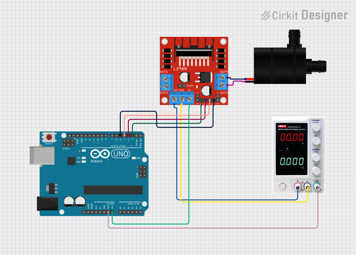
Circuit Documentation
Summary
This circuit is designed to control a water pump using an Arduino UNO and an L298N motor driver. The water pump simulates the flow of blood in the human heart by mimicking the systole (pumping phase) and diastole (relaxation phase) actions. The Arduino UNO is programmed to control the motor driver, which in turn controls the water pump.
Component List
Arduino UNO
- Description: A microcontroller board based on the ATmega328P.
- Pins: UNUSED, IOREF, Reset, 3.3V, 5V, GND, Vin, A0, A1, A2, A3, A4, A5, SCL, SDA, AREF, D13, D12, D11, D10, D9, D8, D7, D6, D5, D4, D3, D2, D1, D0
L298N DC Motor Driver
- Description: A dual H-Bridge motor driver module that allows control of the speed and direction of two DC motors.
- Pins: OUT1, OUT2, 12V, GND, 5V, OUT3, OUT4, 5V-ENA-JMP-I, 5V-ENA-JMP-O, +5V-J1, +5V-J2, ENA, IN1, IN2, IN3, IN4, ENB
Power Supply
- Description: Provides the necessary power to the circuit.
- Pins: +, -, GND
Water Pump
- Description: A small DC water pump used to simulate the flow of blood.
- Pins: VCC, GND
Wiring Details
Arduino UNO
- GND connected to Power Supply GND
- Vin connected to L298N 5V
- D2 connected to L298N IN1
- D3 connected to L298N IN2
- D4 connected to L298N IN3
- D5 connected to L298N IN4
L298N DC Motor Driver
- 5V connected to Arduino UNO Vin
- IN1 connected to Arduino UNO D2
- IN2 connected to Arduino UNO D3
- IN3 connected to Arduino UNO D4
- IN4 connected to Arduino UNO D5
- 12V connected to Power Supply +
- GND connected to Power Supply -
- OUT3 connected to Water Pump GND
- OUT4 connected to Water Pump VCC
Power Supply
- GND connected to Arduino UNO GND
- + connected to L298N 12V
- - connected to L298N GND
Water Pump
- VCC connected to L298N OUT4
- GND connected to L298N OUT3
Code Documentation
/*
 * Arduino Sketch to control a water pump using L298N motor driver
 * to simulate the flow of blood in the human heart.
 *
 * Connections:
 * L298N IN1 -> Arduino D2
 * L298N IN2 -> Arduino D3
 * L298N IN3 -> Arduino D4
 * L298N IN4 -> Arduino D5
 * L298N 5V -> Arduino Vin
 * L298N GND -> Arduino GND
 * L298N OUT4 -> Water Pump VCC
 * L298N OUT3 -> Water Pump GND
 * Power Supply + -> L298N 12V
 * Power Supply - -> L298N GND
 * Power Supply GND -> Arduino GND
 */

const int IN1 = 2;
const int IN2 = 3;
const int IN3 = 4;
const int IN4 = 5;

void setup() {
  // Initialize the motor control pins as outputs
  pinMode(IN1, OUTPUT);
  pinMode(IN2, OUTPUT);
  pinMode(IN3, OUTPUT);
  pinMode(IN4, OUTPUT);
}

void loop() {
  // Simulate the pumping action of the heart
  pumpWater();
}

void pumpWater() {
  // Simulate systole (pumping phase)
  digitalWrite(IN1, HIGH);
  digitalWrite(IN2, LOW);
  digitalWrite(IN3, HIGH);
  digitalWrite(IN4, LOW);
  delay(800); // Adjust delay to match heart pumping speed

  // Simulate diastole (relaxation phase)
  digitalWrite(IN1, LOW);
  digitalWrite(IN2, LOW);
  digitalWrite(IN3, LOW);
  digitalWrite(IN4, LOW);
  delay(800); // Adjust delay to match heart relaxation speed
}
This code initializes the motor control pins as outputs and simulates the pumping action of the heart by controlling the water pump through the L298N motor driver. The pumpWater function alternates between the systole and diastole phases with adjustable delays to match the desired heart pumping speed.