
Arduino UNO and NRF24L01 Wireless Joystick Controller with Pushbutton Inputs
View and Edit Project In Cirkit Designer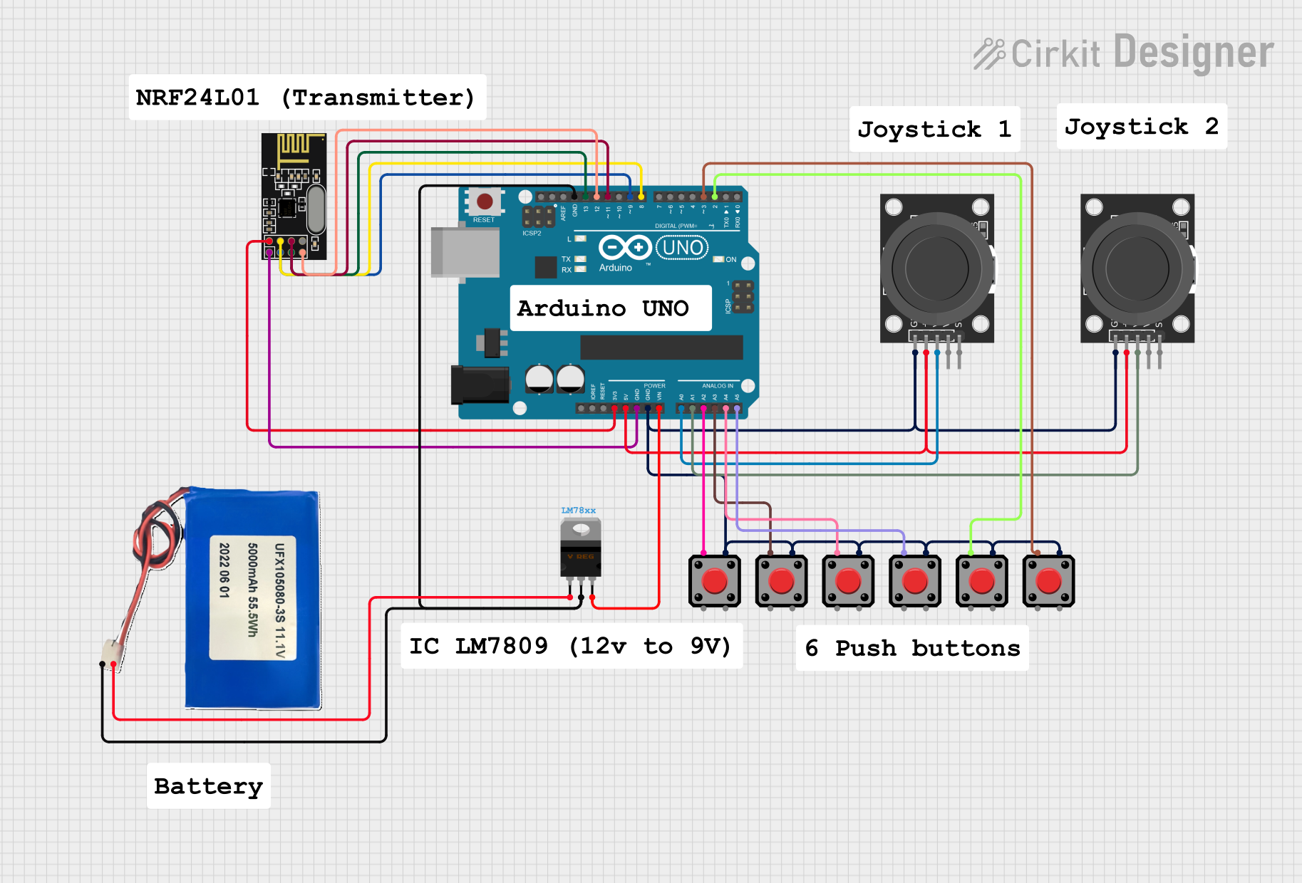
Circuit Documentation
Summary
This circuit involves an Arduino UNO microcontroller interfacing with an NRF24L01 wireless module, two KY-023 Dual Axis Joystick Modules, several pushbuttons, an LM78xx voltage regulator, and a Li-ion 5000mAh battery. The circuit is designed to read inputs from the joysticks and pushbuttons and potentially communicate wirelessly using the NRF24L01 module. The power is regulated using the LM78xx voltage regulator to ensure the Arduino UNO and other components receive the correct voltage.
Component List
Arduino UNO
- Description: A microcontroller board based on the ATmega328P.
- Pins: UNUSED, IOREF, Reset, 3.3V, 5V, GND, Vin, A0, A1, A2, A3, A4, A5, SCL, SDA, AREF, D13, D12, D11, D10, D9, D8, D7, D6, D5, D4, D3, D2, D1, D0
NRF24L01
- Description: A wireless transceiver module for communication.
- Pins: IRQ (not used), MOSI, CSN, VCC (3V), GND, CE, SCK, MISO
KY-023 Dual Axis Joystick Module
- Description: A joystick module with two potentiometers for X and Y axis and a pushbutton.
- Pins: GND, +5V, VRx, VRy, SW
LM78xx Voltage Regulator
- Description: A voltage regulator to provide a stable output voltage.
- Pins: Input, GND, Output
Li-ion 5000mAh
- Description: A rechargeable lithium-ion battery.
- Pins: 11.1V, GND
Pushbutton
- Description: A simple pushbutton switch.
- Pins: Pin 2, Pin 1, Pin 3, Pin 4
Wiring Details
Arduino UNO
- 3.3V: Connected to VCC (3V) of NRF24L01
- 5V: Connected to +5V of both KY-023 Dual Axis Joystick Modules
- GND: Connected to GND of NRF24L01, both KY-023 Dual Axis Joystick Modules, and all pushbuttons
- Vin: Connected to Output of LM78xx Voltage Regulator
- A0: Connected to VRx of one KY-023 Dual Axis Joystick Module
- A1: Connected to VRx of the other KY-023 Dual Axis Joystick Module
- A2: Connected to Pin 1 of one pushbutton
- A3: Connected to Pin 1 of another pushbutton
- A4: Connected to Pin 1 of another pushbutton
- A5: Connected to Pin 1 of another pushbutton
- D13: Connected to SCK of NRF24L01
- D12: Connected to MISO of NRF24L01
- D11: Connected to MOSI of NRF24L01
- D9: Connected to CE of NRF24L01
- D8: Connected to CSN of NRF24L01
- D3: Connected to Pin 1 of another pushbutton
- D2: Connected to Pin 1 of another pushbutton
NRF24L01
- VCC (3V): Connected to 3.3V of Arduino UNO
- GND: Connected to GND of Arduino UNO
- SCK: Connected to D13 of Arduino UNO
- MISO: Connected to D12 of Arduino UNO
- MOSI: Connected to D11 of Arduino UNO
- CE: Connected to D9 of Arduino UNO
- CSN: Connected to D8 of Arduino UNO
KY-023 Dual Axis Joystick Module
- +5V: Connected to 5V of Arduino UNO
- GND: Connected to GND of Arduino UNO
- VRx: One connected to A0 of Arduino UNO, the other connected to A1 of Arduino UNO
LM78xx Voltage Regulator
- Input: Connected to 11.1V of Li-ion 5000mAh
- GND: Connected to GND of Li-ion 5000mAh and Arduino UNO
- Output: Connected to Vin of Arduino UNO
Li-ion 5000mAh
- 11.1V: Connected to Input of LM78xx Voltage Regulator
- GND: Connected to GND of LM78xx Voltage Regulator and Arduino UNO
Pushbutton
- Pin 1: Connected to A2, A3, A4, A5, D3, and D2 of Arduino UNO
- Pin 4: Connected to GND of Arduino UNO
Code Documentation
Arduino UNO Code
sketch.ino
void setup() {
  // put your setup code here, to run once:

}

void loop() {
  // put your main code here, to run repeatedly:

}
documentation.txt
This documentation provides a comprehensive overview of the circuit, including a summary, detailed component list, wiring details, and the code used in the Arduino UNO microcontroller.