
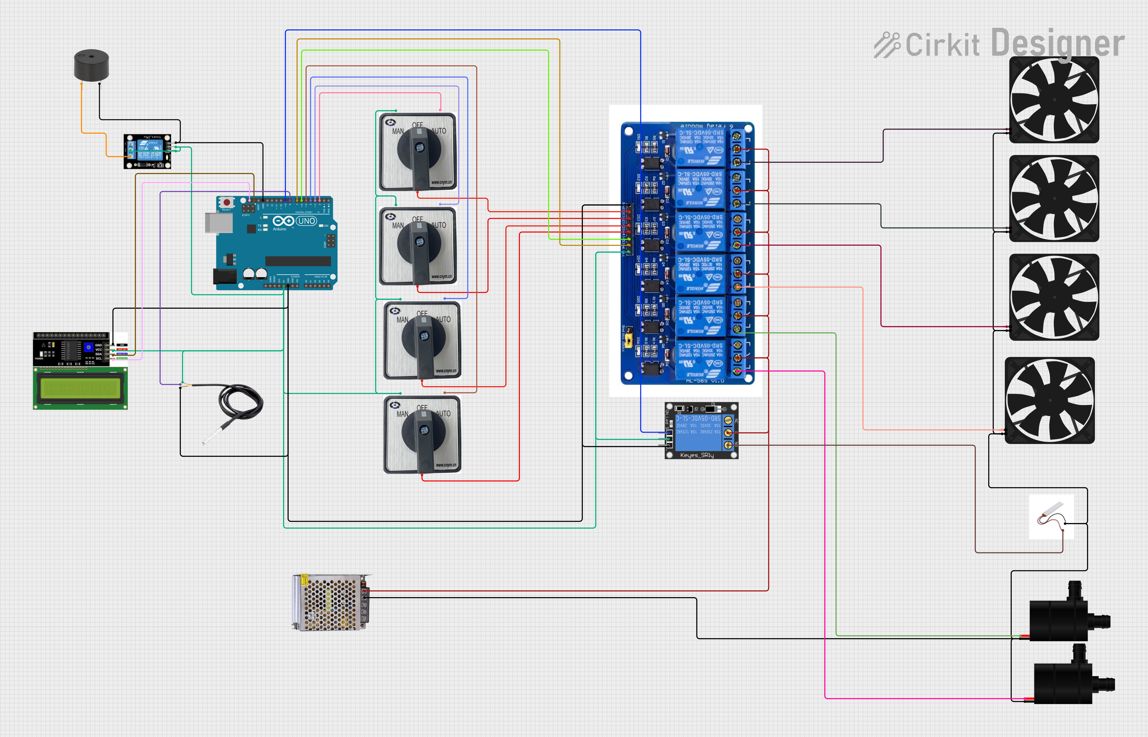
Circuit Documentation
Summary
The circuit in question is designed to control various devices such as fans, a water pump, a heating element, and to monitor temperature using a DS18B20 sensor. It includes selectors for manual and automatic control, a buzzer for alerts, and an LCD I2C display for user interface. The core of the control system is an Arduino UNO microcontroller, which interfaces with a 6-relay module to control the connected devices. The circuit is powered by a 12V 5A power supply, and the Arduino UNO is responsible for the logic control and sensor data processing.
Component List
Selector
- Description: A switch with Manual, Auto, and Keluaran (Output) options for control modes.
- Pins: Manual, Auto, Keluaran
Arduino UNO
- Description: A microcontroller board based on the ATmega328P, used for controlling the logic of the circuit.
- Pins: UNUSED, IOREF, Reset, 3.3V, 5V, GND, Vin, A0-A5, SCL, SDA, AREF, D0-D13
6 Relays Module
- Description: A module with 6 relays to control high power devices.
- Pins: GND, IN1-IN6, VCC, NC_1-NC_6, COM_1-COM_6, NO_1-NO_6
Buzzer
- Description: An audible signaling device.
- Pins: PIN, GND
Fan
- Description: A device used to create airflow.
- Pins: GND, 5V
POWER SUPPLY 12V 5AMP
- Description: Provides the necessary power to the circuit.
- Pins: 220V Positive Pole (AC), 220V Negative Pole (AC), GND, GND (DC), 12V-24V Output (DC)
DS18B20
- Description: A temperature sensor.
- Pins: Signal, GND, VCC
Heating Element
- Description: A device that generates heat through electrical resistance.
- Pins: Not specified
Water Pump
- Description: A device used to move water through the system.
- Pins: VCC, GND
Relay Module 1 Channel
- Description: A single relay module for controlling one device.
- Pins: S, 5V, GND, NC, COM, NO
1-Channel Relay (5V 10A)
- Description: A single relay capable of handling up to 10A at 5V.
- Pins: NC, Signal, C, Power, NO, Ground
LCD I2C Display
- Description: A display module for user interface, using I2C communication.
- Pins: GND, VCC, SDA, SCL
Wiring Details
Selector
- Manual: Connected to 5V power rail.
- Auto: Connected to Arduino UNO digital pins (D2, D3, D4, D5) for different selector instances.
- Keluaran: Connected to relay module inputs (IN1, IN2, IN3, IN4) for different selector instances.
Arduino UNO
- 5V: Powers the 5V rail for other components.
- GND: Common ground for the circuit.
- D2-D5: Control signals for selectors in Auto mode.
- D6, D7: Control signals for relay module IN5 and IN6.
- D8: Reads signal from DS18B20 temperature sensor.
- D9: Control signal for 1-Channel Relay (5V 10A).
- SCL, SDA: I2C communication with LCD I2C Display.
6 Relays Module
- VCC: Connected to 5V power rail.
- GND: Common ground for the circuit.
- IN1-IN6: Control inputs from Arduino UNO and selectors.
- COM_1-COM_6: Connected to 12V-24V power rail.
- NO_1-NO_6: Connected to devices such as fans and water pumps.
Buzzer
- PIN: Connected to Relay module 1 channel NC pin.
- GND: Common ground for the circuit.
Fan
- 5V: Powered by NO pins of the relay module for different fan instances.
- GND: Common ground for the circuit.
POWER SUPPLY 12V 5AMP
- 12V-24V Output (DC): Powers the COM pins of the relay module and the 1-Channel Relay (5V 10A) C pin.
DS18B20
- Signal: Connected to Arduino UNO D8 pin.
- GND: Common ground for the circuit.
- VCC: Connected to 5V power rail.
Heating Element
- Connected to NO pin of the 1-Channel Relay (5V 10A).
Water Pump
- VCC: Powered by NO pins of the relay module for different water pump instances.
- GND: Common ground for the circuit.
Relay Module 1 Channel
- S, 5V: Connected to 5V power rail.
- GND: Common ground for the circuit.
- NC: Connected to buzzer PIN pin.
- COM: Connected to 5V power rail.
1-Channel Relay (5V 10A)
- Power: Connected to 5V power rail.
- Ground: Common ground for the circuit.
- Signal: Controlled by Arduino UNO D9 pin.
- C: Connected to 12V-24V power rail.
- NO: Connected to heating element.
LCD I2C Display
- GND: Common ground for the circuit.
- VCC: Connected to 5V power rail.
- SDA, SCL: I2C communication with Arduino UNO.
Documented Code
Arduino UNO Code (sketch.ino)
void setup() {
  // put your setup code here, to run once:

}

void loop() {
  // put your main code here, to run repeatedly:

}
Additional Notes
- The provided code for the Arduino UNO is a template with empty setup and loop functions. Actual implementation code is required for the circuit to perform its intended functions.
- The documentation.txt file is empty and does not contain any additional information.