Bioamplifier-Integrated ESP32 & Arduino UNO Wi-Fi Controlled Biometric Data Acquisition System
Circuit Documentation
Summary
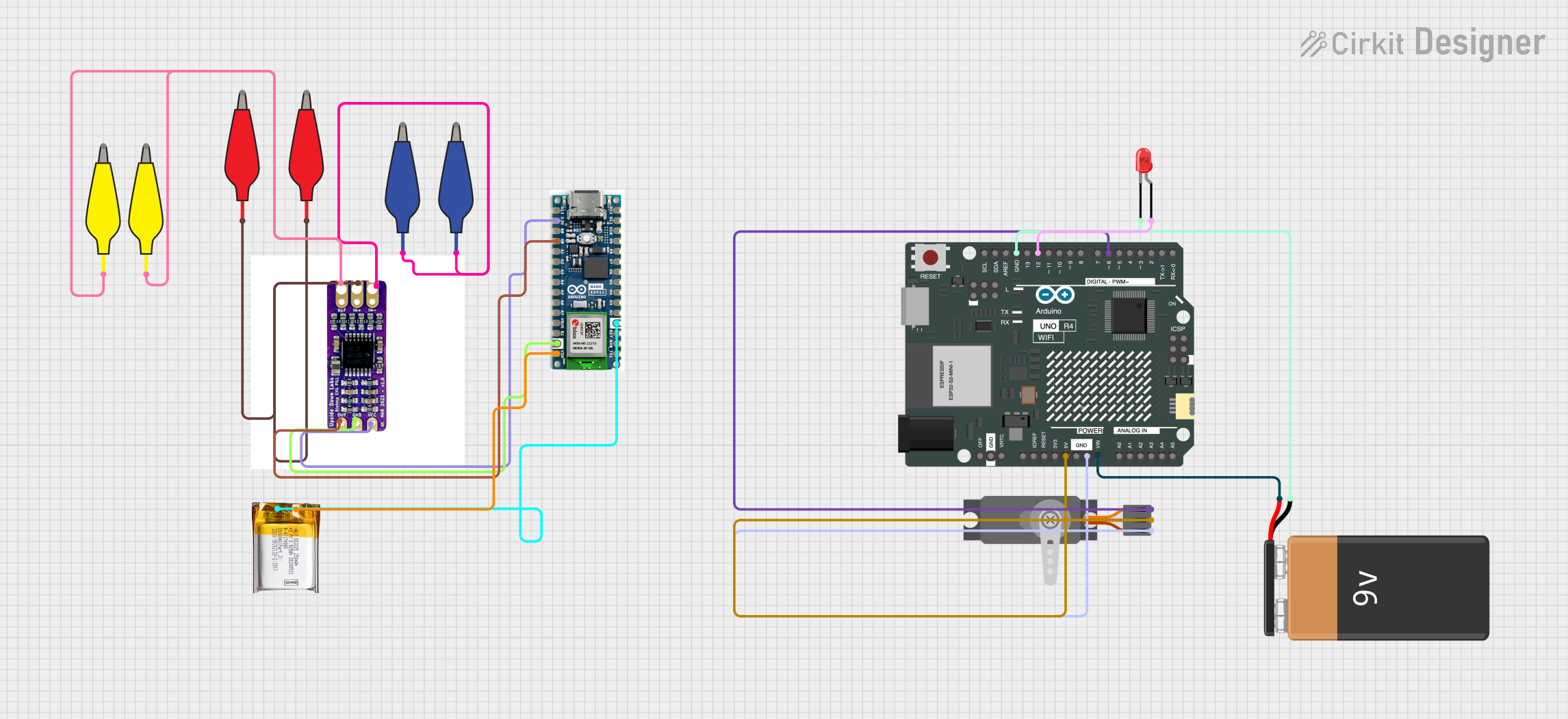
The circuit in question is composed of various electronic components including a bioamplifier (BioAmp EXG Pill), two microcontrollers (Arduino Nano ESP32 and Arduino UNO R4 WiFi), a 3.7V LiPo battery, a 9V battery, a servo motor, an LED, and several alligator clip cables. The circuit is designed to capture bioelectrical signals using the BioAmp EXG Pill, process these signals with the Arduino Nano ESP32, and perform actions such as driving a servo motor and lighting an LED with the Arduino UNO R4 WiFi. Power is supplied to the circuit through the LiPo and 9V batteries.
Component List
BioAmp EXG Pill
- A bioamplifier designed to read bioelectrical signals.
- Pins: VCC, out, GND, Electrode 1, Electrode 2, Electrode 3
Arduino Nano ESP32
- A compact microcontroller with WiFi capabilities.
- Pins: D12, D11, D10, D9, D8, D7, D6, D5, D4, D3, D2, GND, RST, RX0, TX1, D13, 3.3V, B0, A0, A1, A2, A3, A4, A5, A6, A7, VBUS, B1, VIN
Alligator Clip Cables (Yellow, Blue, Red)
- Used for making quick and temporary electrical connections.
- Pins: Pin, Alligator
3.7v LiPo Battery
- A rechargeable battery providing a power source for the circuit.
- Pins: +Ve, GND
Arduino UNO R4 WiFi
- A microcontroller board with WiFi capabilities.
- Pins: OFF, GND, VRTC, IIC0_SCL, IIC0_SDA, 3V3, GPIO 41, GPIO 0, GPIO 42, GPIO 43, GPIO 44, BOOT, IOREF, RESET, 5V, VIN, A0, A1, A2, A3, A4, A5, RSPCKA, CIPO, COPI, D0/RX, D1/TX, D2, D3, D4, D5, D6, D7, D8, D9, D10, D11, D12, D13, AREF, SDA, SCL
LED: Two Pin (Red)
- A red light-emitting diode used as an indicator or for illumination.
- Pins: Cathode, Anode
Servo (Wokwi Compatible)
- An actuator for precise control of angular position.
- Pins: GND, V+, PWM
9V Battery
- A standard battery providing a power source for the circuit.
- Pins: -, +
Wiring Details
BioAmp EXG Pill
- VCC connected to Arduino Nano ESP32 3.3V
- out connected to Arduino Nano ESP32 A0
- GND connected to Arduino Nano ESP32 GND
- Electrode 1 connected to blue alligator clip cables
- Electrode 2 connected to red alligator clip cables
- Electrode 3 connected to yellow alligator clip cables
Arduino Nano ESP32
- 3.3V connected to BioAmp EXG Pill VCC
- A0 connected to BioAmp EXG Pill out
- GND connected to BioAmp EXG Pill GND and 3.7v LiPo GND
- VIN connected to 3.7v LiPo +Ve
Alligator Clip Cables
- Used to connect BioAmp EXG Pill electrodes to the subject.
3.7v LiPo Battery
- +Ve connected to Arduino Nano ESP32 VIN
- GND connected to Arduino Nano ESP32 GND
Arduino UNO R4 WiFi
- 5V connected to Servo V+
- GND connected to Servo GND and LED cathode
- VIN connected to 9V Battery +
- D6 connected to Servo PWM
- D12 connected to LED anode
LED: Two Pin (Red)
- Anode connected to Arduino UNO R4 WiFi D12
- Cathode connected to 9V Battery - and Arduino UNO R4 WiFi GND
Servo (Wokwi Compatible)
- V+ connected to Arduino UNO R4 WiFi 5V
- GND connected to Arduino UNO R4 WiFi GND
- PWM connected to Arduino UNO R4 WiFi D6
9V Battery
- connected to Arduino UNO R4 WiFi VIN
- connected to LED cathode and Arduino UNO R4 WiFi GND
Documented Code
Arduino UNO R4 WiFi Code (sketch.ino)
void setup() {
  // put your setup code here, to run once:

}

void loop() {
  // put your main code here, to run repeatedly:

}
Note: The provided code for the Arduino UNO R4 WiFi is a template with empty setup and loop functions. This code should be expanded with the necessary logic to control the servo and LED based on the signals processed by the Arduino Nano ESP32.
Additional Files
- A text file named "documentation.txt" is mentioned, but it contains no code or information.