
Arduino UNO-Based Smart Parking System with RFID and IR Sensors
View and Edit Project In Cirkit Designer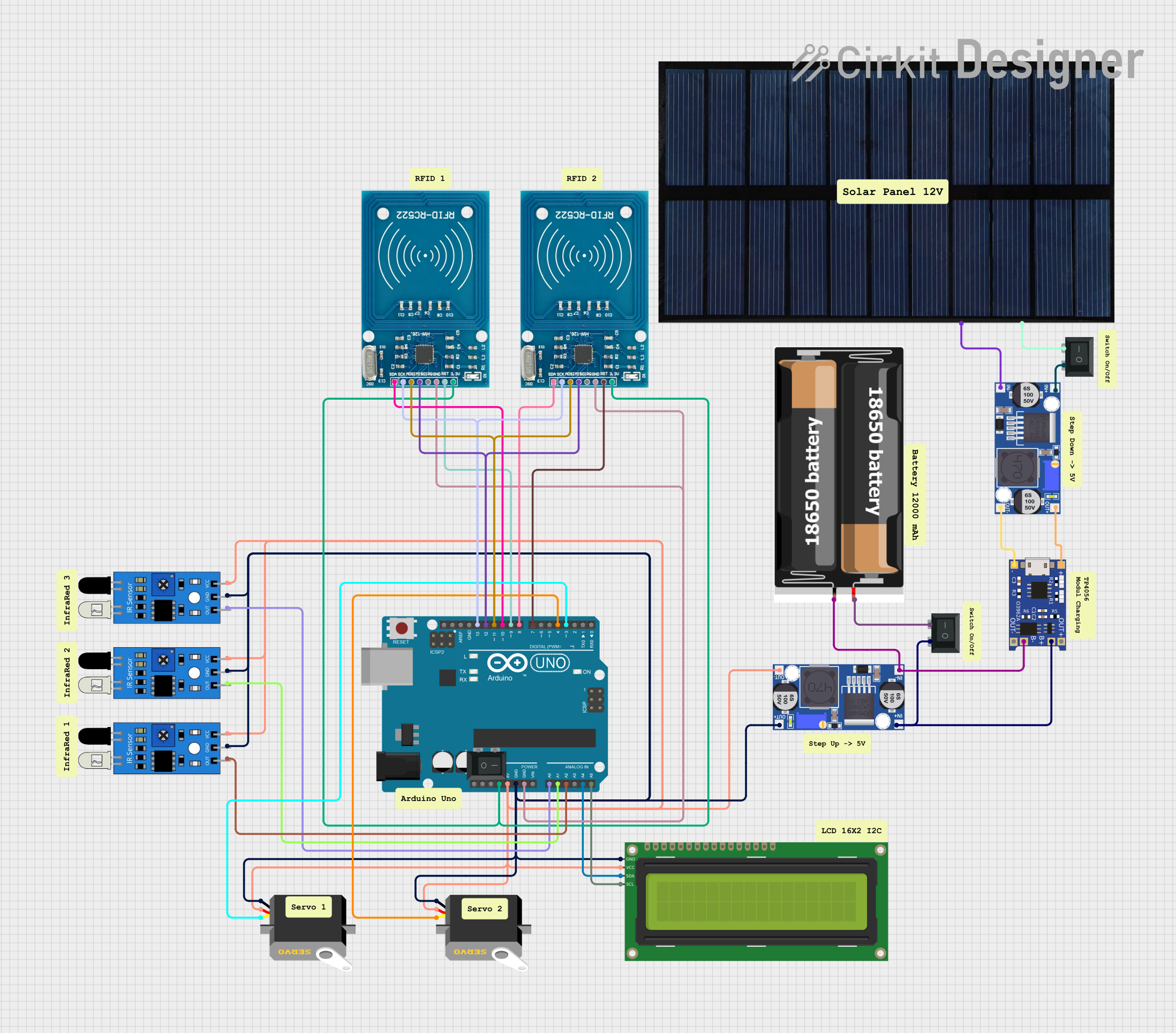
Circuit Documentation
Summary
This circuit is designed to manage a parking system using an Arduino UNO microcontroller. The system includes RFID readers for entry and exit, IR sensors to detect parking slot occupancy, servos to control entry and exit barriers, and an LCD to display the number of available and occupied parking slots. The circuit is powered by a combination of a solar cell, 18650 batteries, and a buck converter for voltage regulation.
Component List
Arduino UNO
- Description: Microcontroller board based on the ATmega328P.
- Pins: UNUSED, IOREF, Reset, 3.3V, 5V, GND, Vin, A0, A1, A2, A3, A4, A5, SCL, SDA, AREF, D13, D12, D11, D10, D9, D8, D7, D6, D5, D4, D3, D2, D1, D0
Rocker Switch (SPST)
- Description: Single Pole Single Throw switch.
- Pins: 1, 2
16x2 I2C LCD
- Description: 16x2 character LCD with I2C interface.
- Pins: GND, VCC, SDA, SCL
RFID-RC522
- Description: RFID reader module.
- Pins: VCC (3.3V), RST, GND, IRQ, MISO, MOSI, SCK, SDA
Servo
- Description: Servo motor.
- Pins: gnd, vcc, pulse
2x 18650
- Description: Battery pack with two 18650 batteries.
- Pins: vcc, gnd
Solar cell
- Description: Solar cell for power generation.
- Pins: +, -
Buck converter
- Description: DC-DC buck converter for voltage regulation.
- Pins: IN+, IN-, OUT+, OUT-
TP4056
- Description: Lithium battery charger module.
- Pins: OUT-, B-, B+, OUT+, IN-, IN+
IR Sensor
- Description: Infrared sensor for object detection.
- Pins: out, gnd, vcc
Wiring Details
Arduino UNO
- 3.3V: Connected to VCC (3.3V) of both RFID-RC522 modules.
- 5V: Connected to VCC of IR sensors, servos, and 16x2 I2C LCD.
- GND: Connected to GND of IR sensors, servos, 16x2 I2C LCD, and both RFID-RC522 modules.
- A0: Connected to out pin of IR sensor 1.
- A1: Connected to out pin of IR sensor 2.
- A2: Connected to out pin of IR sensor 3.
- A4: Connected to SDA pin of 16x2 I2C LCD.
- A5: Connected to SCL pin of 16x2 I2C LCD.
- D3: Connected to pulse pin of Servo 1.
- D4: Connected to pulse pin of Servo 2.
- D7: Connected to RST pin of RFID-RC522 (second module).
- D8: Connected to SDA pin of RFID-RC522 (second module).
- D9: Connected to RST pin of RFID-RC522 (first module).
- D10: Connected to SDA pin of RFID-RC522 (first module).
- D11: Connected to MOSI pin of both RFID-RC522 modules.
- D12: Connected to MISO pin of both RFID-RC522 modules.
- D13: Connected to SCK pin of both RFID-RC522 modules.
Rocker Switch (SPST)
- Pin 1: Connected to IN+ of Buck converter.
- Pin 2: Connected to VCC of 2x 18650 battery pack.
16x2 I2C LCD
- GND: Connected to GND of Arduino UNO.
- VCC: Connected to 5V of Arduino UNO.
- SDA: Connected to A4 of Arduino UNO.
- SCL: Connected to A5 of Arduino UNO.
RFID-RC522
- VCC (3.3V): Connected to 3.3V of Arduino UNO.
- GND: Connected to GND of Arduino UNO.
- SCK: Connected to D13 of Arduino UNO.
- MISO: Connected to D12 of Arduino UNO.
- MOSI: Connected to D11 of Arduino UNO.
- SDA: Connected to D10 (first module) and D8 (second module) of Arduino UNO.
- RST: Connected to D9 (first module) and D7 (second module) of Arduino UNO.
Servo
- gnd: Connected to GND of Arduino UNO.
- vcc: Connected to 5V of Arduino UNO.
- pulse: Connected to D3 (first servo) and D4 (second servo) of Arduino UNO.
2x 18650
- vcc: Connected to pin 2 of Rocker Switch (SPST).
- gnd: Connected to B- of TP4056 and IN- of Buck converter.
Solar cell
- +: Connected to pin 2 of Rocker Switch (SPST).
- -: Connected to IN- of Buck converter.
Buck converter
- IN+: Connected to pin 1 of Rocker Switch (SPST).
- IN-: Connected to B- of TP4056 and gnd of 2x 18650 battery pack.
- OUT+: Connected to GND of Arduino UNO.
- OUT-: Connected to 5V of Arduino UNO.
TP4056
- B+: Connected to IN+ of Buck converter.
- B-: Connected to IN- of Buck converter and gnd of 2x 18650 battery pack.
- IN+: Connected to OUT+ of Buck converter.
- IN-: Connected to OUT- of Buck converter.
IR Sensor
- vcc: Connected to 5V of Arduino UNO.
- gnd: Connected to GND of Arduino UNO.
- out: Connected to A0 (first sensor), A1 (second sensor), and A2 (third sensor) of Arduino UNO.
Code Documentation
#include <Wire.h>
#include <LiquidCrystal_I2C.h>
#include <Servo.h>
#include <SPI.h>
#include <MFRC522.h>

#define SS_PIN_1 10  // Pin SDA RFID pertama
#define RST_PIN_1 9  // Pin RST RFID pertama
#define SS_PIN_2 8   // Pin SDA RFID kedua
#define RST_PIN_2 7  // Pin RST RFID kedua

MFRC522 rfid1(SS_PIN_1, RST_PIN_1);
MFRC522 rfid2(SS_PIN_2, RST_PIN_2);

LiquidCrystal_I2C lcd(0x27, 16, 2);

Servo servoMasuk;
Servo servoKeluar;

#define SERVO_MASUK_PIN 3
#define SERVO_KELUAR_PIN 4
#define IR1 A0
#define IR2 A1
#define IR3 A2

int slotParkir = 3; // Total slot parkir
int parkirKosong = slotParkir;

void setup() {
  Serial.begin(9600);
  SPI.begin();
  rfid1.PCD_Init();
  rfid2.PCD_Init();

  servoMasuk.attach(SERVO_MASUK_PIN);
  servoKeluar.attach(SERVO_KELUAR_PIN);
  servoMasuk.write(0);  // Palang awal tertutup
  servoKeluar.write(0); // Palang awal tertutup

  pinMode(IR1, INPUT);
  pinMode(IR2, INPUT);
  pinMode(IR3, INPUT);

  lcd.init();
  lcd.backlight();
  updateLCD();
}

void loop() {
  // RFID 1: Akses Masuk
  if (rfid1.PICC_IsNewCardPresent() && rfid1.PICC_ReadCardSerial()) {
    Serial.println("Kartu terdeteksi di pintu masuk!");
    bukaPalangMasuk();
    delay(5000);
    tutupPalangMasuk();
    rfid1.PICC_HaltA();
  }

  // RFID 2: Akses Keluar
  if (rfid2.PICC_IsNewCardPresent() && rfid2.PICC_ReadCardSerial()) {
    Serial.println("Kartu terdeteksi di pintu keluar!");
    bukaPalangKeluar();
    delay(5000);
    tutupPalangKeluar();
    rfid2.PICC_HaltA();
  }

  // Deteksi slot parkir
  int ir1 = digitalRead(IR1);
  int ir2 = digitalRead(IR2);
  int ir3 = digital