
Arduino Nano Controlled Robotic Vehicle with Excavator Functions
View and Edit Project In Cirkit Designer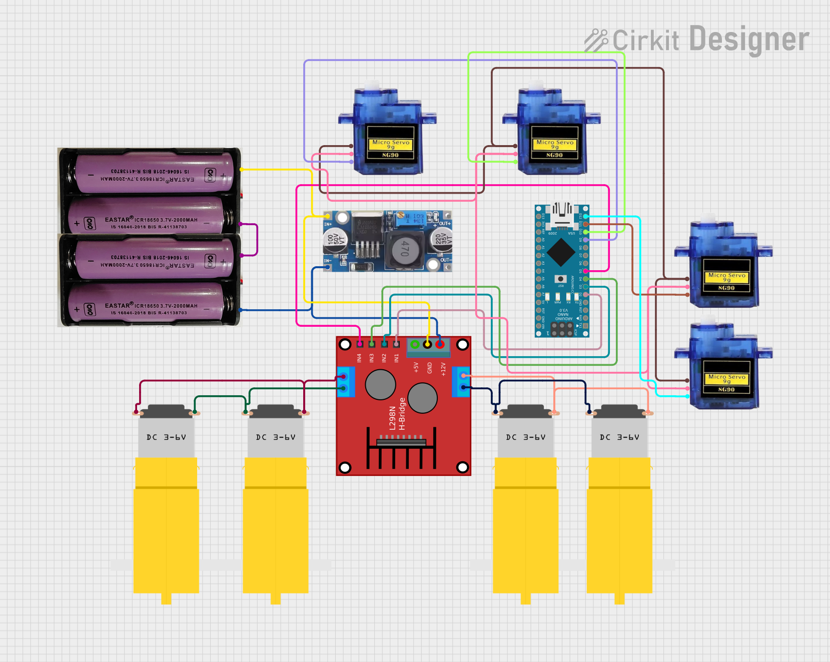
Circuit Documentation
Summary
The circuit in question is designed to control a set of four micro servos and two DC motors through an Arduino Nano microcontroller. The micro servos are controlled via PWM signals, while the DC motors are driven by an H-bridge (ponte h) that allows for direction control. A step-down buck converter is used to regulate the voltage from two 7.4V batteries to a suitable level for the microcontroller and servos. The Arduino Nano is programmed to interpret serial commands to manipulate the servos and control the motion of the motors, enabling forward, backward, left, and right movements.
Component List
Arduino Nano
- Microcontroller board based on the ATmega328P
- It has a variety of digital and analog I/O pins for interfacing with various components.
Micro Servo 9G (x4)
- Small and lightweight servo motors for precise control
- Operates on +5V and uses a PWM signal for position control.
Ponte H (H-Bridge)
- An electronic circuit that enables a voltage to be applied across a load in either direction
- Used for controlling the direction of DC motors.
Step Down Buck Converter
- A DC-DC converter that steps down voltage from a higher level to a lower level
- Ensures that the microcontroller and servos receive the correct operating voltage.
Motor Amarillo Motorreductor Hobby (x4)
- Yellow DC gear motors used for driving wheels or other mechanical parts
- Operates on a voltage provided by the H-bridge.
7.4V Batteries (x2)
- Provide the power source for the circuit
- Their voltage is stepped down for the microcontroller and servos, and directly used for the H-bridge.
Wiring Details
Arduino Nano
- D2 connected to IN1 on the H-bridge
- D3 connected to IN2 on the H-bridge
- D4 connected to IN3 on the H-bridge
- D5 connected to IN4 on the H-bridge
- D9 connected to PWM on the first Micro Servo 9G
- D10 connected to PWM on the second Micro Servo 9G
- D11/MOSI connected to PWM on the third Micro Servo 9G
- D12/MISO connected to PWM on the fourth Micro Servo 9G
Micro Servo 9G
- All servos have their GND pins interconnected
- All servos have their +5V pins interconnected
- Each servo's PWM pin is connected to a designated digital pin on the Arduino Nano
Ponte H (H-Bridge)
- IN1 to IN4 connected to digital pins D2 to D5 on the Arduino Nano
- OUT1 and OUT2 connected to the first pair of Motor Amarillo Motorreductor Hobby
- OUT3 and OUT4 connected to the second pair of Motor Amarillo Motorreductor Hobby
- 5V and GND connected to the corresponding power rails
- 12V connected to the positive terminal of the 7.4V battery
Step Down Buck Converter
- IN + connected to the positive terminal of the first 7.4V battery
- IN - GND connected to the negative terminal of the second 7.4V battery
- OUT + and OUT - GND provide regulated voltage to the microcontroller and servos
Motor Amarillo Motorreductor Hobby
- Each motor's vcc and GND pins are connected to the corresponding OUT pins on the H-bridge
7.4V Batteries
- The positive terminal of one battery is connected to the IN + of the buck converter
- The negative terminal of the other battery is connected to the IN - GND of the buck converter
- The batteries are also connected in series to provide 12V to the H-bridge
Documented Code
#include<Servo.h>

#define RightForward 2
#define RightBackward 3
#define LeftForward 4
#define LeftBackward 5

char val;
int check = 1;

int Dmservo = 90;
int Dbservo = 0;
int Daservo = 20;
int Doservo = 140;

Servo mservo;
Servo aservo;
Servo bservo;
Servo oservo;

void setup(){
  Serial.begin(9600);

  bservo.attach(12);
  aservo.attach(11);
  mservo.attach(10);
  oservo.attach(9);

  pinMode(RightForward,OUTPUT);
  pinMode(RightBackward,OUTPUT);
  pinMode(LeftForward,OUTPUT);
  pinMode(LeftBackward,OUTPUT);

  bservo.write(Dbservo);
  aservo.write(Daservo);
  mservo.write(Dmservo);
  oservo.write(Doservo);
}

void loop(){

  if(Serial.available()){
    val = Serial.read();
    Serial.println(val);

    if(val == 'X'){
      check = 0;
    }
    if(val == 'x'){
      check = 1;
    }

    if(check == 1){
       car();
    }
    if(check == 0){
      excavator();
    }

  }

}

void excavator(){

  if(val == 'G'){
    Dbservo += 2;
    bservo.write(Dbservo);
  }
  if(val == 'I'){
    Dbservo -=2;
    bservo.write(Dbservo);
  }
  if(val == 'F'){
    Daservo +=2;
    aservo.write(Daservo);
  }

  if(val == 'B'){
    Daservo-=2;
    aservo.write(Daservo);
  }

  if(val == 'R'){
    Dmservo -=2;
    mservo.write(Dmservo);
  }

  if(val == 'L'){
    Dmservo +=2;
    mservo.write(Dmservo);
  }

  if(val == 'J'){
    Doservo +=2;
    oservo.write(Doservo);
  }
  if(val == 'H'){
    Doservo -=2;
    oservo.write(Doservo);

  }

}

void car(){

  if(val == 'F'){
    forward();
  }
  if(val == 'B'){
    backward();
  }
  if(val == 'R'){
    right();
  }
  if(val == 'L'){
    left();
  }
  if(val == 'S'){
    stop();
  }
  if(val == 'I'){
    right();
  }
  if(val == 'G'){
    left();
  }
  if(val == 'J'){
    left();
  }
  if(val == 'H'){
    right();
  }

}

void forward(){
  digitalWrite(RightForward,HIGH);
  digitalWrite(LeftForward,HIGH);

  digitalWrite(RightBackward,LOW);
  digitalWrite(LeftBackward,LOW);
}

void backward(){
  digitalWrite(RightForward,LOW);
  digitalWrite(LeftForward,LOW);

  digitalWrite(RightBackward,HIGH);
  digitalWrite(LeftBackward,HIGH);
}

void right(){
  digitalWrite(RightForward,LOW);
  digitalWrite(LeftForward,HIGH);

  digitalWrite(RightBackward,HIGH);
  digitalWrite(LeftBackward,LOW);
}

void left(){
  digitalWrite(RightForward,HIGH);
  digitalWrite(LeftForward,LOW);

  digitalWrite(RightBackward,LOW);
  digitalWrite(LeftBackward,HIGH);
}

void stop(){
  digitalWrite(RightForward,LOW);
  digitalWrite(LeftForward,LOW);

  digitalWrite(RightBackward,LOW);
  digitalWrite(LeftBackward,LOW);
}
This code is designed to control the movement of a vehicle with two DC motors and manipulate the position of four servos. It listens for serial input and adjusts the motor direction and servo positions accordingly.