
Arduino-Based Smart Access Control System with Bluetooth and GSM Connectivity
View and Edit Project In Cirkit Designer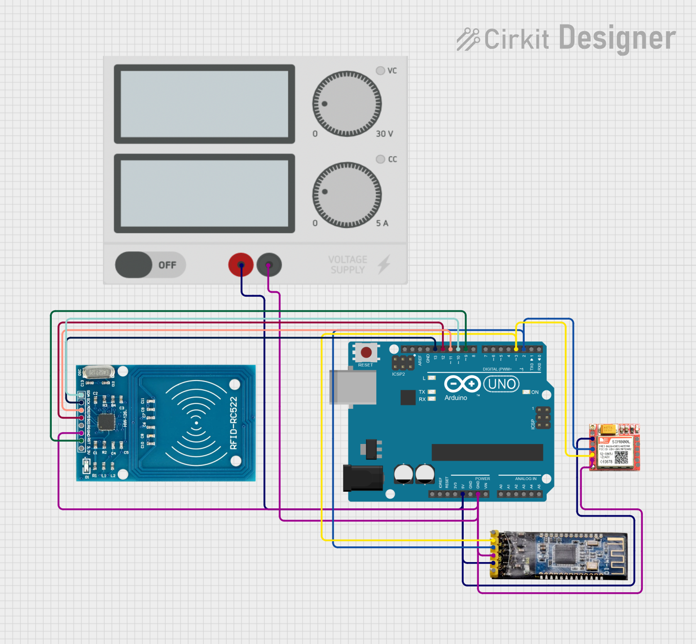
Circuit Documentation
Summary
This document provides a detailed overview of a circuit that integrates an Arduino UNO, a Bluetooth module HM-10, a SIM 800L module, an RFID-RC522 module, and a Power Supply. The circuit is designed to facilitate communication between these components, with the Arduino UNO acting as the central microcontroller.
Component List
Arduino UNO
- Description: A microcontroller board based on the ATmega328P.
- Pins: UNUSED, IOREF, Reset, 3.3V, 5V, GND, Vin, A0, A1, A2, A3, A4, A5, SCL, SDA, AREF, D13, D12, D11, D10, D9, D8, D7, D6, D5, D4, D3, D2, D1, D0
Bluetooth module HM-10
- Description: A Bluetooth Low Energy (BLE) module.
- Pins: BRK, RX, TX, GND, VCC, State
SIM 800L
- Description: A GSM/GPRS module for communication over cellular networks.
- Pins: NFT, RING, VCC, DTR, RST, MIC +, RXD, MIC-, TXD, SPK+, GND, SPK-
Power Supply
- Description: Provides power to the circuit.
- Pins: +, -
RFID-RC522
- Description: A low-cost RFID module for reading and writing RFID tags.
- Pins: VCC (3.3V), RST, GND, IRQ, MISO, MOSI, SCK, SDA
Wiring Details
Arduino UNO
- 5V: Connected to VCC of SIM 800L, VCC of Bluetooth module HM-10, and + of Power Supply.
- GND: Connected to GND of SIM 800L, GND of Bluetooth module HM-10, - of Power Supply, and GND of RFID-RC522.
- D13: Connected to SCK of RFID-RC522.
- D12: Connected to MISO of RFID-RC522.
- D11: Connected to MOSI of RFID-RC522.
- D10: Connected to SDA of RFID-RC522.
- D9: Connected to RST of RFID-RC522.
- D3: Connected to TXD of SIM 800L and RX of Bluetooth module HM-10.
- D2: Connected to RXD of SIM 800L and TX of Bluetooth module HM-10.
Bluetooth module HM-10
- VCC: Connected to 5V of Arduino UNO and + of Power Supply.
- GND: Connected to GND of Arduino UNO, - of Power Supply, and GND of SIM 800L.
- RX: Connected to D3 of Arduino UNO and TXD of SIM 800L.
- TX: Connected to D2 of Arduino UNO and RXD of SIM 800L.
SIM 800L
- VCC: Connected to 5V of Arduino UNO and + of Power Supply.
- GND: Connected to GND of Arduino UNO, - of Power Supply, and GND of Bluetooth module HM-10.
- TXD: Connected to D3 of Arduino UNO and RX of Bluetooth module HM-10.
- RXD: Connected to D2 of Arduino UNO and TX of Bluetooth module HM-10.
Power Supply
- +: Connected to 5V of Arduino UNO, VCC of SIM 800L, and VCC of Bluetooth module HM-10.
- -: Connected to GND of Arduino UNO, GND of SIM 800L, GND of Bluetooth module HM-10, and GND of RFID-RC522.
RFID-RC522
- VCC (3.3V): Not connected in this circuit.
- GND: Connected to GND of Arduino UNO, - of Power Supply, and GND of Bluetooth module HM-10.
- SCK: Connected to D13 of Arduino UNO.
- MISO: Connected to D12 of Arduino UNO.
- MOSI: Connected to D11 of Arduino UNO.
- SDA: Connected to D10 of Arduino UNO.
- RST: Connected to D9 of Arduino UNO.
Documented Code
Arduino UNO Code
void setup() {
  // put your setup code here, to run once:

}

void loop() {
  // put your main code here, to run repeatedly:

}
This code initializes the Arduino UNO but does not contain any specific functionality. It serves as a template for further development.