Cirkit Designer
Your all-in-one circuit design IDE
Home /
Project Documentation
Raspberry Pi Pico and RP2040-Based Multi-Color LED Control with MPU6050 Integration
Circuit Documentation
Summary
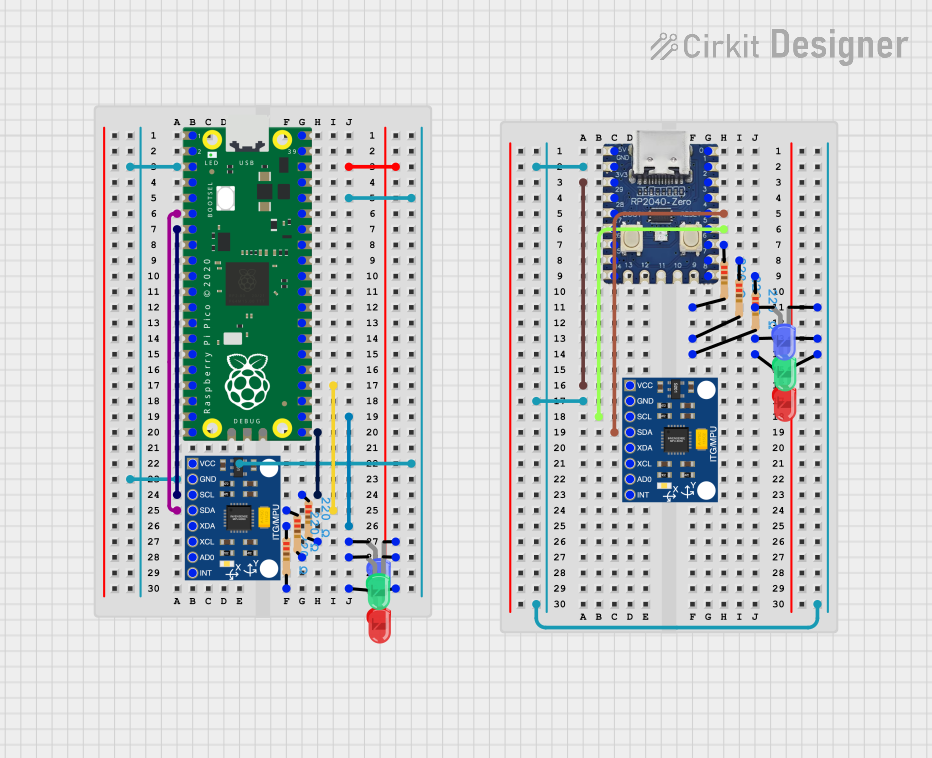
This circuit involves a Raspberry Pi Pico and an RP2040 microcontroller interfacing with multiple LEDs and MPU6050 sensors. The circuit includes resistors to limit current to the LEDs. The Raspberry Pi Pico and RP2040 are used to control the LEDs and read data from the MPU6050 sensors.
Component List
Raspberry Pi Pico
- Description: A microcontroller board based on the RP2040 microcontroller chip.
- Pins: 43 pins including GPIO, power, and ground pins.
RP2040
- Description: A microcontroller chip used in the Raspberry Pi Pico.
- Pins: 16 pins including GPIO, power, and ground pins.
LED: Two Pin (blue)
- Description: A blue LED with two pins: anode and cathode.
LED: Two Pin (red)
- Description: A red LED with two pins: anode and cathode.
LED: Two Pin (green)
- Description: A green LED with two pins: anode and cathode.
InvenSense MPU6050
- Description: A 6-axis motion tracking device with accelerometer and gyroscope.
- Pins: VCC, GND, SCL, SDA, XDA, XCL, AD0, INT.
Resistor (220 Ohms)
- Description: A resistor with a resistance of 220 Ohms.
- Pins: Two pins.
Wiring Details
Raspberry Pi Pico
- pin 3 connected to GND of InvenSense MPU6050.
- pin 6 connected to SDA of InvenSense MPU6050.
- pin 7 connected to SCL of InvenSense MPU6050.
- pin 21 connected to pin1 of Resistor.
- pin 22 connected to pin1 of Resistor.
- pin 24 connected to pin1 of Resistor.
- pin 36 connected to VCC of InvenSense MPU6050.
- pin 38 connected to cathode of LED: Two Pin (blue), LED: Two Pin (red), and LED: Two Pin (green).
RP2040
- GND connected to GND of InvenSense MPU6050, cathode of LED: Two Pin (red), LED: Two Pin (green), and LED: Two Pin (blue).
- 3V3 connected to VCC of InvenSense MPU6050.
- pin 5 connected to SDA of InvenSense MPU6050.
- pin 6 connected to SCL of InvenSense MPU6050.
- pin 7 connected to pin1 of Resistor.
- pin 8 connected to pin1 of Resistor.
InvenSense MPU6050
- GND connected to pin 3 of Raspberry Pi Pico and GND of RP2040.
- VCC connected to pin 36 of Raspberry Pi Pico and 3V3 of RP2040.
- SDA connected to pin 6 of Raspberry Pi Pico and pin 5 of RP2040.
- SCL connected to pin 7 of Raspberry Pi Pico and pin 6 of RP2040.
LED: Two Pin (blue)
- cathode connected to pin 38 of Raspberry Pi Pico.
- anode connected to pin2 of Resistor.
LED: Two Pin (red)
- cathode connected to pin 38 of Raspberry Pi Pico.
- anode connected to pin2 of Resistor.
LED: Two Pin (green)
- cathode connected to pin 38 of Raspberry Pi Pico.
- anode connected to pin2 of Resistor.
Resistor (220 Ohms)
- pin1 connected to pin 21, pin 22, pin 24 of Raspberry Pi Pico, and pin 7, pin 8 of RP2040.
- pin2 connected to anode of LED: Two Pin (blue), LED: Two Pin (red), and LED: Two Pin (green).
Documented Code
Raspberry Pi Pico Code
void setup() {
  // put your setup code here, to run once:

}

void loop() {
  // put your main code here, to run repeatedly:

}
RP2040 Code
No code provided for the RP2040 microcontroller.