Cirkit Designer
Your all-in-one circuit design IDE
Home /
Project Documentation
Arduino Mega 2560-Based Environmental Monitoring System with Multiple Sensors
Circuit Documentation
Summary
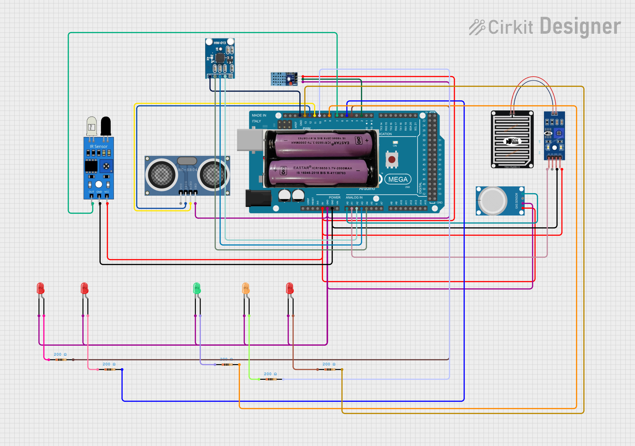
This document provides a detailed overview of a circuit designed using an Arduino Mega 2560 microcontroller. The circuit includes various sensors, LEDs, and resistors, all interconnected to perform specific functions. The document includes a component list, wiring details, and the embedded code used in the microcontroller.
Component List
Arduino Mega 2560
- Description: A microcontroller board based on the ATmega2560.
- Pins: IOREF, RESET, 3V3, 5V, GND, VIN, A0-A15, D21/SCL, D20/SDA, D19/RX1, D18/TX1, D17 PWM/RX2, D16 PWM/TX2, D15/RX3, D14/TX3, D0 RX0, D1 TX0, D2 PWM-D13 PWM, AREF, SDA, SCL, D22-D53.
7.4v Battery
- Description: A 7.4V power source.
- Pins: +, -
DHT 11
- Description: A digital temperature and humidity sensor.
- Pins: VCC, GND, DATA
Rain Sensor
- Description: A sensor to detect rain.
- Pins: AO, DO, GRD, VCC
AITrip ADXL335 GY-61
- Description: A 3-axis accelerometer.
- Pins: GND, Z-Out, Y-Out, X-Out, VCC
IR Sensor
- Description: An infrared sensor for object detection.
- Pins: out, gnd, vcc
HC-SR04 Ultrasonic Distance Sensor
- Description: An ultrasonic sensor for measuring distance.
- Pins: VCC, TRIG, ECHO, GND
MQ-4
- Description: A gas sensor for methane detection.
- Pins: A0, D0, GND, VCC
LED: Two Pin (Red)
- Description: A red LED.
- Pins: cathode, anode
LED: Two Pin (Green)
- Description: A green LED.
- Pins: cathode, anode
LED: Two Pin (Orange)
- Description: An orange LED.
- Pins: cathode, anode
Resistor
- Description: A resistor with a resistance of 200 Ohms.
- Pins: pin1, pin2
Wiring Details
Arduino Mega 2560
- 5V: Connected to VCC of DHT 11, IR Sensor, MQ-4, Rain Sensor.
- GND: Connected to GND of DHT 11, HC-SR04, IR Sensor, MQ-4, Rain Sensor, AITrip ADXL335, and cathode of all LEDs.
- A0: Connected to A0 of MQ-4.
- A1: Connected to AO of Rain Sensor.
- A2: Connected to X-Out of AITrip ADXL335.
- A3: Connected to Y-Out of AITrip ADXL335.
- A4: Connected to Z-Out of AITrip ADXL335.
- D2 PWM: Connected to DATA of DHT 11.
- D4 PWM: Connected to pin2 of a Resistor.
- D5 PWM: Connected to pin2 of a Resistor.
- D7 PWM: Connected to out of IR Sensor.
- D8 PWM: Connected to pin2 of a Resistor.
- D10 PWM: Connected to pin2 of a Resistor.
- D11 PWM: Connected to ECHO of HC-SR04.
- D12 PWM: Connected to TRIG of HC-SR04.
- D13 PWM: Connected to pin2 of a Resistor.
DHT 11
- VCC: Connected to 5V of Arduino Mega 2560.
- GND: Connected to GND of Arduino Mega 2560.
- DATA: Connected to D2 PWM of Arduino Mega 2560.
Rain Sensor
- VCC: Connected to 5V of Arduino Mega 2560.
- GRD: Connected to GND of Arduino Mega 2560.
- AO: Connected to A1 of Arduino Mega 2560.
AITrip ADXL335 GY-61
- VCC: Connected to 5V of Arduino Mega 2560.
- GND: Connected to GND of Arduino Mega 2560.
- X-Out: Connected to A2 of Arduino Mega 2560.
- Y-Out: Connected to A3 of Arduino Mega 2560.
- Z-Out: Connected to A4 of Arduino Mega 2560.
IR Sensor
- vcc: Connected to 5V of Arduino Mega 2560.
- gnd: Connected to GND of Arduino Mega 2560.
- out: Connected to D7 PWM of Arduino Mega 2560.
HC-SR04 Ultrasonic Distance Sensor
- VCC: Connected to 5V of Arduino Mega 2560.
- GND: Connected to GND of Arduino Mega 2560.
- ECHO: Connected to D11 PWM of Arduino Mega 2560.
- TRIG: Connected to D12 PWM of Arduino Mega 2560.
MQ-4
- VCC: Connected to 5V of Arduino Mega 2560.
- GND: Connected to GND of Arduino Mega 2560.
- A0: Connected to A0 of Arduino Mega 2560.
LED: Two Pin (Red)
- cathode: Connected to GND of Arduino Mega 2560.
- anode: Connected to pin1 of a Resistor.
LED: Two Pin (Green)
- cathode: Connected to GND of Arduino Mega 2560.
- anode: Connected to pin1 of a Resistor.
LED: Two Pin (Orange)
- cathode: Connected to GND of Arduino Mega 2560.
- anode: Connected to pin1 of a Resistor.
Resistor
- pin1: Connected to anode of an LED.
- pin2: Connected to D4 PWM, D5 PWM, D8 PWM, D10 PWM, D13 PWM of Arduino Mega 2560.
Code
sketch.ino
void setup() {
  // put your setup code here, to run once:

}

void loop() {
  // put your main code here, to run repeatedly:

}
documentation.txt