
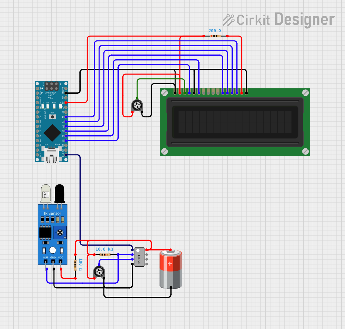
Circuit Documentation
Summary
This circuit is designed to interface an Arduino Nano with various sensors and an LCD display to create an anemometer system. The anemometer measures wind speed and direction, displaying the results on the LCD. The system includes trimmer potentiometers for calibration, resistors for current limiting and voltage division, an LM358 operational amplifier for signal conditioning, and an IR sensor for detecting wind speed and direction. The Arduino Nano serves as the central processing unit, running the embedded code to read sensor data, calculate wind parameters, and manage the LCD display output.
Component List
Arduino Nano
- Microcontroller board based on the ATmega328P
- Provides digital and analog I/O pins
- Used for controlling the entire system
Trimmer Potentiometer (x2)
- Variable resistor with a knob for adjustment
- Used for calibration or setting reference voltages
Resistor (100 Ohms)
- Fixed resistor used for current limiting or voltage division
Resistor (10k Ohms)
- Fixed resistor used for current limiting or voltage division
Resistor (200 Ohms)
- Fixed resistor used for current limiting or voltage division
IR Sensor
- Sensor for detecting objects or motion
- Used for measuring wind speed and direction
LM358
- Dual operational amplifier for signal amplification and conditioning
LCD Display (16 pin)
- Alphanumeric liquid crystal display
- Used for displaying wind speed and direction
5V Battery
- Power source for the circuit
Wiring Details
Arduino Nano
GNDconnected to system ground5Vconnected to 5V from the resistor and trimmer potentiometerA0toA5connected to LCD Display data and control pinsD13/SCKconnected to LM358 output
Trimmer Potentiometer
leg1connected to 5V supplywiperconnected to LCD display contrast or LM358 inputleg2connected to system ground
Resistor (100 Ohms, 10k Ohms, 200 Ohms)
- One end connected to a voltage source or signal line
- The other end connected to ground, a load, or another signal line
IR Sensor
outconnected to LM358 inputgndconnected to system groundvccconnected to 5V supply through a resistor
LM358
OUTPUT 1connected to Arduino NanoD13/SCKINPUT+connected to IR sensor output through a resistorINPUT-connected to IR sensor outputVEE, GNDconnected to system groundVCCconnected to 5V supply
LCD Display (16 pin)
VSSandKconnected to system groundVDDconnected to 5V supplyVOconnected to trimmer potentiometer wiperRS,E,DB4toDB7connected to Arduino NanoA0toA5R_Wconnected to system groundAconnected to 5V through a resistor
5V Battery
+connected to 5V supply line-connected to system ground
Documented Code
#include <LiquidCrystal.h>

LiquidCrystal lcd(A0, A1, A2, A3, A4, 3);

#define Sensor1 11
#define Sensor2 10
#define Sensor3 9
#define Sensor4 2
#define Sensor5 4
#define Sensor6 5
#define Sensor7 12
#define Sensor8 A5
#define Sensor9 13

float t, t1, t2;
float windSpeed;

bool state = true;
bool count = true;

int S1 = 0;
int S2 = 0;
int S3 = 0;
int S4 = 0;
int S5 = 0;
int S6 = 0;
int S7 = 0;
int S8 = 0;
int S9 = 0;

void setup() {
  Serial.begin(9600);  // start serial for output
  lcd.begin(16, 2);
  pinMode(Sensor1, INPUT);
  pinMode(Sensor2, INPUT);
  pinMode(Sensor3, INPUT);
  pinMode(Sensor4, INPUT);
  pinMode(Sensor5, INPUT);
  pinMode(Sensor6, INPUT);
  pinMode(Sensor7, INPUT);
  pinMode(Sensor8, INPUT);
  pinMode(Sensor9, INPUT);

  lcd.setCursor(0, 0);
  lcd.print("Arduino Based ");
  lcd.setCursor(0, 1);
  lcd.print("Anemometer");
  delay(3000);
  lcd.clear();
}

void loop() {

  if (state == 0)
  {
    if (count == 0)
    {
      readSensor();
      windDirection();
      if (S9 == 1)
      {
        t2 = millis();
        t = t2 - t1;
        t = t / 1000;
        windSpeed = (2 * 3.1416 * 0.0001 * 3600) / t ;
        lcd.setCursor(0, 0);
        lcd.print("Wind: ");
        lcd.print(windSpeed);
        lcd.print("kmh");
        count = true;
      }
    }

    else {
      readSensor();
      windDirection();
      if (S9 == 0)
      {
        t1 = millis();
        count = false;
      }
    }
  }
  else
  {
    readSensor();
    windDirection();
//   Serialprint();
    if (S9 == 1)
    {
      state = 0;
    }
    lcd.setCursor(0, 0);
    lcd.print("Wind: ");
    lcd.print("0 ");
    lcd.print("kmh");
    lcd.setCursor(0, 1);
    lcd.print("Direction:");
  }
}

void readSensor()
{
  S1 = digitalRead(Sensor1);
  S2 = digitalRead(Sensor2);
  S3 = digitalRead(Sensor3);
  S4 = digitalRead(Sensor4);
  S5 = digitalRead(Sensor5);
  S6 = digitalRead(Sensor6);
  S7 = digitalRead(Sensor7);
  S8 = digitalRead(Sensor8);
  S9 = digitalRead(Sensor9);
}

void windDirection()
{
  if (S7 == 1)
  {
    lcd.setCursor(10, 1);
    lcd.print("0");
    lcd.write(223);
    lcd.print("N   ");
  }
  else if (S8 == 1)
  {
    lcd.setCursor(10, 1);
    lcd.print("45");
    lcd.write(223);
    lcd.print("NE ");
  }
  else if (S1 == 1)
  {
    lcd.setCursor(10, 1);
    lcd.print("90");
    lcd.write(223);
    lcd.print("E  ");
  }

  else if (S2 == 1)
  {
    lcd.setCursor(10, 1);
    lcd.print("135");
    lcd.write(223);
    lcd.print("SE");
  }
  else if (S3 == 1)
  {
    lcd.setCursor(10, 1);
    lcd.print("180");
    lcd.write(223);
    lcd.print("S ");
  }
  else if (S4 == 1)
  {
    lcd.setCursor(10, 1);
    lcd.print("225");
    lcd.write(223);
    lcd.print("SW");
  }
  else if (S5 == 1)
  {
    lcd.setCursor(10, 1);
    lcd.print("270");
    lcd.write(223);
    lcd.print("W ");
  }
  else if (S6 == 1)
  {
    lcd.setCursor(10, 1);
    lcd.print("315");
    lcd.write(223);
    lcd.print("NW");
  }

}

void Serialprint()
{
  Serial.print(S1);
  lcd.setCursor(0, 0);
  lcd.print(S1);
  Serial.print("\t");
  lcd.setCursor(1, 0);
  Serial.print(S2);
  lcd.print(S2);
  Serial.print("\t");
  lcd.setCursor(2, 0);
  Serial.print(S3);
  lcd.print(S3);
  Serial.print("\t");
  Serial.print(S4);
  lcd.print(S4);
  Serial.print("\t");
  Serial.print(S5);
  lcd.print(S5);
  Serial.print("\t");
  Serial.print(S6);
  lcd.print(S6);
  Serial.print("\t");
  Serial.print(S7);
  lcd.print(S7);
  Serial.print("\t");
  Serial.print(S8);
  lcd.print(S8);
  Serial.print("\t");
  Serial.print(S9);
  lcd.print(S9);
  Serial.println("\t");
}
This code initializes the LCD and configures the Arduino's digital pins as inputs for the sensors. It includes functions to read the sensor states and determine the wind direction. The main loop manages the state of the anemometer, reads sensor data, calculates wind speed, and updates the LCD display accordingly.