
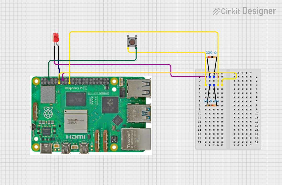
Circuit Documentation
Summary of the Circuit
This circuit is designed to control a red two-pin LED using a pushbutton, interfaced with a Raspberry Pi 5. The LED blinks when the pushbutton is not pressed and stays continuously on when the pushbutton is pressed. The circuit includes two resistors, one for current limiting to the LED and another as a pull-up for the pushbutton. The Raspberry Pi 5 is programmed to control the LED based on the state of the pushbutton.
Component List
LED: Two Pin (red)
- Pins: cathode, anode
- Description: A red LED that lights up when current flows from the anode to the cathode.
Resistor (220 Ohms)
- Pins: pin1, pin2
- Description: A resistor with a resistance of 220 Ohms, used for current limiting to the LED.
Resistor (10k Ohms)
- Pins: pin1, pin2
- Description: A resistor with a resistance of 10k Ohms, used as a pull-up resistor for the pushbutton.
Raspberry Pi 5
- Pins: Type-C, Micro HDMI 1, Micro HDMI 2, Camera 1, Camera 2, PoE, Fan, PCIe, USB 3.0, USB 2.0, Ethernet, 5V, GND, 3.3v, GPIO 14, GPIO 15, GPIO 18, GPIO 23, GPIO 24, GPIO 25, GPIO 8, GPIO 7, GPIO 1, GPIO 12, GPIO 16, GPIO 20, GPIO 21, GPIO 2, GPIO 3, GPIO 4, GPIO 17, GPIO 27, GPIO 22, GPIO 10, GPIO 9, GPIO 11, GPIO 0, GPIO 5, GPIO 6, GPIO 13, GPIO 19, GPIO 26
- Description: A microcontroller board used to control the LED and read the state of the pushbutton.
Pushbutton
- Pins: Pin 3 (out), Pin 4 (out), Pin 1 (in), Pin 2 (in)
- Description: A momentary pushbutton used to control the state of the LED.
Wiring Details
LED: Two Pin (red)
- Cathode connected to GND of Raspberry Pi 5 and one end of the 220 Ohm resistor.
- Anode connected to GPIO 18 of Raspberry Pi 5.
Resistor (220 Ohms)
- Pin1 connected to the cathode of the LED.
- Pin2 connected to GND of Raspberry Pi 5.
Resistor (10k Ohms)
- Pin1 connected to GPIO 17 of Raspberry Pi 5 and Pin 2 (in) of the Pushbutton.
- Pin2 connected to 3.3v of Raspberry Pi 5.
Raspberry Pi 5
- GPIO 18 connected to the anode of the LED.
- GPIO 17 connected to one end of the 10k Ohm resistor and Pin 2 (in) of the Pushbutton.
- GND connected to one end of the 220 Ohm resistor.
- 3.3v connected to one end of the 10k Ohm resistor.
Pushbutton
- Pin 2 (in) connected to GPIO 17 of Raspberry Pi 5 and one end of the 10k Ohm resistor.
- Pin 4 (out) connected to GND of Raspberry Pi 5.
Documented Code
/*
 * This Arduino Sketch controls an LED using a push button.
 * The LED blinks when the push button is NOT pressed.
 * The LED stays on continuously when the push button IS pressed.
 */

#include <Arduino.h>

// Define pin numbers
const int LED_PIN = 18;
const int BUTTON_PIN = 17;

void setup() {
  // Initialize the LED pin as an output
  pinMode(LED_PIN, OUTPUT);
  // Initialize the button pin as an input with pull-up resistor
  pinMode(BUTTON_PIN, INPUT_PULLUP);
}

void loop() {
  // Read the state of the button
  int buttonState = digitalRead(BUTTON_PIN);

  if (buttonState == HIGH) {
    // Button is NOT pressed, blink the LED
    digitalWrite(LED_PIN, HIGH); // Turn LED on
    delay(500); // Wait for 500 milliseconds
    digitalWrite(LED_PIN, LOW); // Turn LED off
    delay(500); // Wait for 500 milliseconds
  } else {
    // Button IS pressed, keep the LED on
    digitalWrite(LED_PIN, HIGH);
  }
}
Filename: sketch.ino
This code is written for the Raspberry Pi 5, which is assumed to be compatible with Arduino syntax and libraries. The code initializes the GPIO pins, reads the state of the pushbutton, and controls the LED accordingly.