
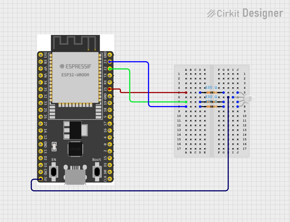
Circuit Documentation
Summary
This circuit consists of an ESP32 Wroom Dev Kit microcontroller, an RGB LED, and three resistors. The ESP32 controls the RGB LED through GPIO pins, with each color channel (Red, Green, Blue) connected through a resistor to limit the current. The common pin of the RGB LED is connected to the 5V supply from the ESP32.
Component List
RGB LED (Wokwi compatible)
- Pins: R, COM, G, B
- Description: RGB LED with common anode
- Purpose: To display different colors by mixing red, green, and blue light
Resistor (330 Ohms)
- Pins: pin1, pin2
- Description: 330 Ohm resistor
- Purpose: Current limiting resistor for the Red channel of the RGB LED
Resistor (330 Ohms)
- Pins: pin1, pin2
- Description: 330 Ohm resistor
- Purpose: Current limiting resistor for the Green channel of the RGB LED
Resistor (330 Ohms)
- Pins: pin1, pin2
- Description: 330 Ohm resistor
- Purpose: Current limiting resistor for the Blue channel of the RGB LED
ESP32 Wroom Dev Kit
- Pins: 3V3, EN, VP, VN, GPIO 34, GPIO 35, GPIO 32, GPIO 33, GPIO 25, GPIO 26, GPIO 27, GPIO 14, GND, GPIO 13, SD2, SD3, CMD, V5, GPIO 23, GPIO 22, TXD, RXD, GPIO 21, GPIO 19, GPIO 18, GPIO 5, GPIO 17, GPIO 16, GPIO 4, GPIO 0, GPIO 2, GPIO 15, SD1, SD0, CLK
- Description: Microcontroller development board
- Purpose: To control the RGB LED
Wiring Details
RGB LED (Wokwi compatible)
- COM connected to V5 of ESP32 Wroom Dev Kit
- R connected to pin2 of Resistor (330 Ohms)
- G connected to pin2 of Resistor (330 Ohms)
- B connected to pin2 of Resistor (330 Ohms)
Resistor (330 Ohms)
- pin1 connected to GPIO 21 of ESP32 Wroom Dev Kit
- pin2 connected to R of RGB LED (Wokwi compatible)
Resistor (330 Ohms)
- pin1 connected to GPIO 22 of ESP32 Wroom Dev Kit
- pin2 connected to G of RGB LED (Wokwi compatible)
Resistor (330 Ohms)
- pin1 connected to GPIO 23 of ESP32 Wroom Dev Kit
- pin2 connected to B of RGB LED (Wokwi compatible)
ESP32 Wroom Dev Kit
- V5 connected to COM of RGB LED (Wokwi compatible)
- GPIO 21 connected to pin1 of Resistor (330 Ohms)
- GPIO 22 connected to pin1 of Resistor (330 Ohms)
- GPIO 23 connected to pin1 of Resistor (330 Ohms)
Code
No code is provided for this circuit.