
ESP32-Controlled Water Heating and Management System with Quality Monitoring
View and Edit Project In Cirkit Designer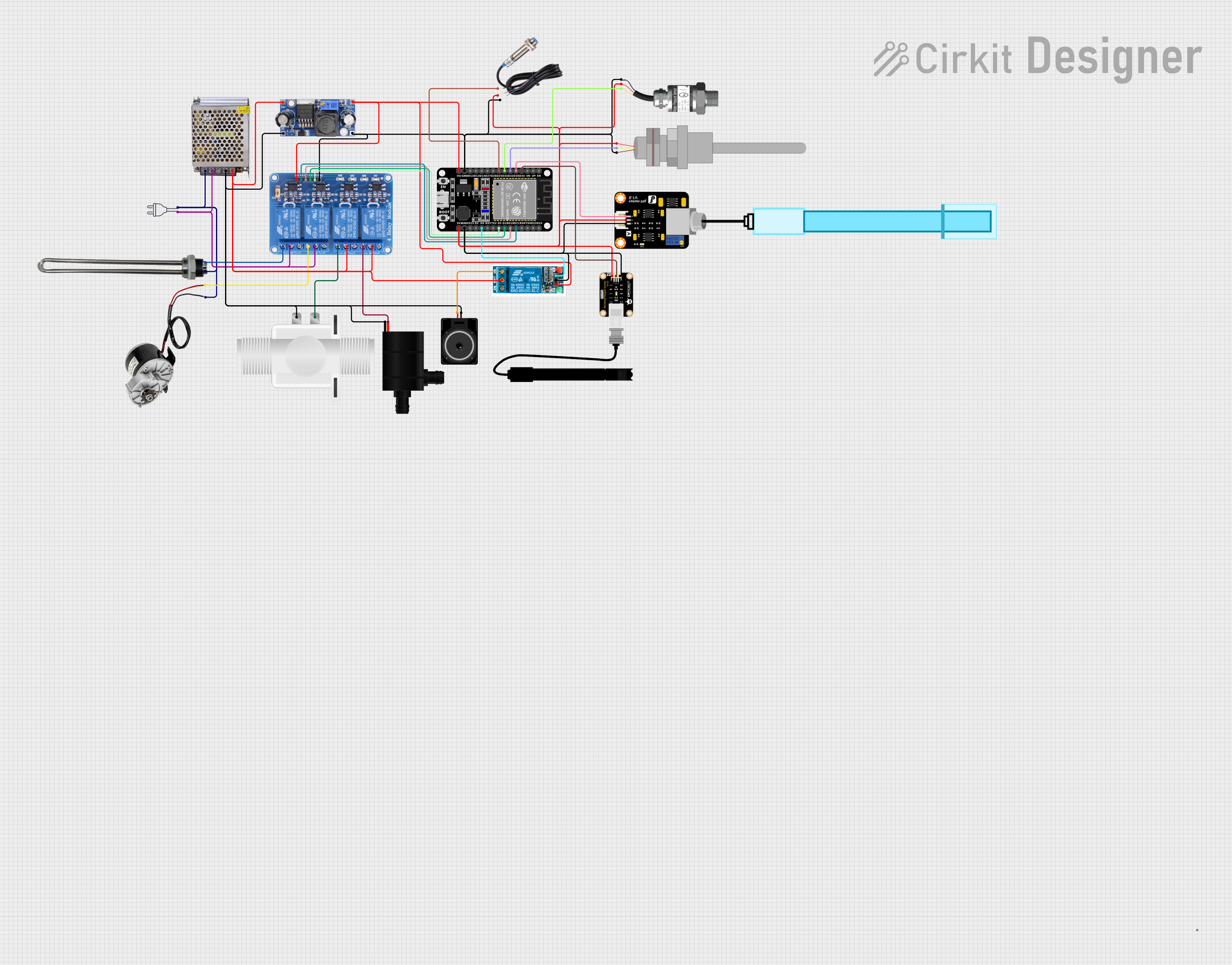
Circuit Documentation
Summary
This circuit is designed to control a water heating system with various sensors and actuators. It includes a power supply unit, a microcontroller, sensors for water quality and temperature, a water pump, a solenoid valve, a water heater, and an electric motor. The system is controlled by an ESP32 microcontroller, which manages the sensors and actuators through a series of relays. The power supply converts 220V AC to 12V DC, which is then stepped down to 5V DC for the microcontroller and sensors. The circuit is designed to ensure safe operation of the water heating system with controlled activation of the water heater and pump, and monitoring of water quality and pressure.
Component List
- Power 220v: This is the main power source for the circuit, providing 220V AC.
- POWER SUPPLY 12V 5AMP: Converts 220V AC to 12V DC to power the components.
- DC DC Converter: Steps down the voltage from 12V to 5V DC for the microcontroller and other low-voltage components.
- Water Heater: An electric heater to increase the water temperature.
- Plastic Solenoid Valve: Controls the flow of water through the system.
- Water Pump: Circulates water through the system.
- ESP32 (30 pin): The microcontroller that manages the sensors and actuators.
- PH Meter: Measures the pH level of the water.
- PT100: A temperature sensor to monitor the water temperature.
- Gravity: Analog Water Pressure Sensor: Monitors the water pressure in the system.
- Inductive Sensor: Detects the presence of metal objects, possibly for safety or control purposes.
- 250W 12V ELECTRIC MOTOR BRUSH MOTOR DC: Provides mechanical power for the system.
- Relay 4 Channel 5v: Controls high power devices with low voltage signals from the microcontroller.
- 5v Relay: A single-channel relay for controlling power to one device.
- Loudspeaker: Outputs audio signals, possibly for alerts or notifications.
- Do Sensor: Likely a dissolved oxygen sensor for water quality monitoring.
Wiring Details
Power 220v
- Hot Wire: Connected to the 220V Positive Pole (AC) of the POWER SUPPLY 12V 5AMP.
- Neutral Wire: Connected to the 220V Negative Pole (AC) of the POWER SUPPLY 12V 5AMP.
POWER SUPPLY 12V 5AMP
- 220V Positive Pole (AC): Connected to the Water Heater and the 250W 12V ELECTRIC MOTOR BRUSH MOTOR DC.
- 220V Negative Pole (AC): Connected to the COM3 and COM4 of the Relay 4 Channel 5v.
- GND (DC): Connected to the GND IN of the DC DC Converter, Water Pump, and Loudspeaker.
- 12V-24V Output (DC): Connected to the +VCC IN of the DC DC Converter and COM1 and COM2 of the Relay 4 Channel 5v.
DC DC Converter
- +VCC IN: Connected to the 12V-24V Output (DC) of the POWER SUPPLY 12V 5AMP.
- GND IN: Connected to the GND (DC) of the POWER SUPPLY 12V 5AMP.
- +VCC OUT: Connected to the VCC of the Relay 4 Channel 5v, Vin of the ESP32, and VCC of the 5v Relay.
- GND OUT: Connected to the GND of the Relay 4 Channel 5v, GND of the ESP32, and various sensors.
Water Heater
- V+: Connected to the NO4 of the Relay 4 Channel 5v.
- V-: Connected to the 220V Positive Pole (AC) of the POWER SUPPLY 12V 5AMP.
Plastic Solenoid Valve
- Pin1: Connected to the NO2 of the Relay 4 Channel 5v.
- Pin2: Connected to the GND (DC) of the POWER SUPPLY 12V 5AMP.
Water Pump
- VCC: Connected to the NO1 of the Relay 4 Channel 5v.
- GND: Connected to the GND (DC) of the POWER SUPPLY 12V 5AMP.
ESP32 (30 pin)
- Vin: Connected to the +VCC OUT of the DC DC Converter.
- GND: Connected to the GND OUT of the DC DC Converter and various sensors.
- 3V3: Powers the Gravity: Analog Water Pressure Sensor, Inductive Sensor, Do Sensor, PH Meter, and PT100.
- D4: Controls the 5v Relay.
- D5, D18, D19, D21: Control the Relay 4 Channel 5v.
- D25: Reads the signal from the Inductive Sensor.
- D32: Reads the signal from the PT100.
- D33: Reads the signal from the Gravity: Analog Water Pressure Sensor.
- D34: Reads the signal from the Do Sensor.
- D35: Reads the signal from the PH Meter.
Relay 4 Channel 5v
- GND: Connected to the GND OUT of the DC DC Converter.
- VCC: Connected to the +VCC OUT of the DC DC Converter.
- IN1, IN2, IN3, IN4: Controlled by the ESP32.
- COM1, COM2, COM3, COM4: Connected to the 12V-24V Output (DC) of the POWER SUPPLY 12V 5AMP and the 220V Negative Pole (AC).
- NO1: Connected to the Water Pump.
- NO2: Connected to the Plastic Solenoid Valve.
- NO3: Connected to the 250W 12V ELECTRIC MOTOR BRUSH MOTOR DC.
- NO4: Connected to the Water Heater.
5v Relay
- GND: Connected to the GND of the ESP32.
- VCC: Connected to the +VCC OUT of the DC DC Converter.
- In: Controlled by the ESP32.
- Normally Open: Connected to the Loudspeaker.
Loudspeaker
- Pin1: Connected to the GND (DC) of the POWER SUPPLY 12V 5AMP.
- Pin2: Connected to the Normally Open of the 5v Relay.
Sensors (PH Meter, Do Sensor, PT100, Gravity: Analog Water Pressure Sensor, Inductive Sensor)
- Signal: Connected to various GPIO pins on the ESP32 for data reading.
- VCC: Powered by the 3V3 pin of the ESP32.
- GND: Connected to the GND OUT of the DC DC Converter.
Documented Code
No code was provided for the microcontroller (ESP32). The code would typically include initialization of GPIO pins, setup of communication protocols (e.g., I2C, SPI, UART), control logic for the relays, and routines for reading sensor data and responding to sensor thresholds or external commands.