Arduino-Controlled Robotic Vehicle with IR Obstacle Detection and L298N Motor Driver
Circuit Documentation
Summary
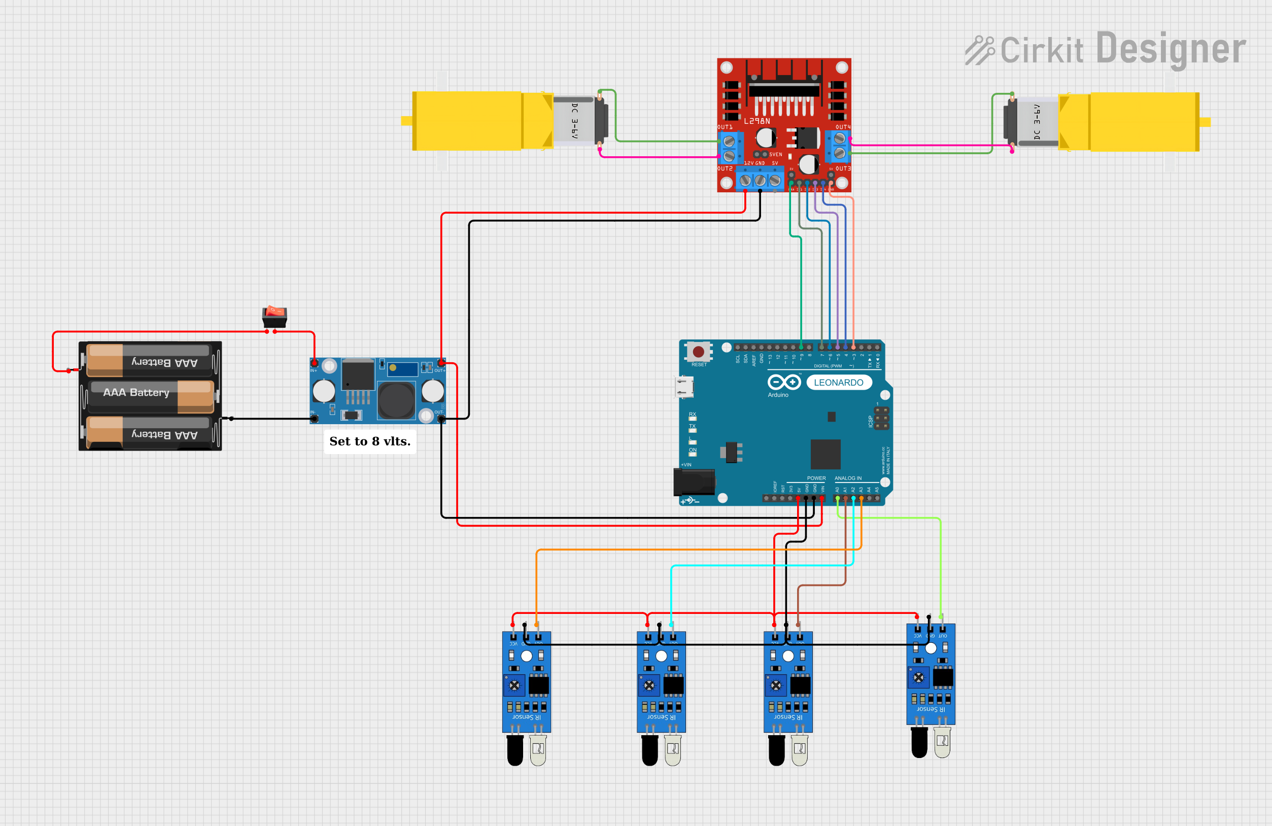
This circuit is designed to control two DC gearmotors using an L298N DC motor driver, which is interfaced with an Arduino Leonardo microcontroller. The power supply for the motor driver is regulated by an LM2596 Step Down Module, which steps down the voltage from a 3xAA battery pack. The circuit also includes four IR sensors for input, which are connected to the analog pins of the Arduino. A rocker switch is used to control the power supply from the battery pack to the step-down module.
Component List
L298N DC Motor Driver
- Description: A module used to control the direction and speed of DC motors.
- Pins: OUT1, OUT2, 12V, GND, 5V, OUT3, OUT4, 5V-ENA-JMP-I, 5V-ENA-JMP-O, +5V-J1, +5V-J2, ENA, IN1, IN2, IN3, IN4, ENB
LM2596 Step Down Module
- Description: A voltage regulator that steps down input voltage to a lower output voltage.
- Pins: OUT-, OUT+, IN-, IN+
Gearmotor DC / Motorreductor
- Description: A DC motor with a gearbox for increased torque.
- Pins: Pin1, Pin2
Arduino Leonardo (Rev3b)
- Description: A microcontroller board based on the ATmega32u4.
- Pins: D0/RX, D1/TX, D2/SDA, D3 PWM/SCL, D4/A6, D5 PWM, D6 PWM/A7, D7, n.c., IOREF, RESET, 3V3, 5V, GND, VIN, A0, A1, A2, A3, A4, A5, D8/A8, D9 PWM/A9, D10 PWM/A10, D11 PWM, D12/A11, D13 PWM, AREF, SDA, SCL
3xAA Battery
- Description: A battery pack consisting of three AA batteries.
- Pins: VCC, GND
IR Sensor
- Description: An infrared sensor used for detecting obstacles or receiving IR signals.
- Pins: out, gnd, vcc
Rocker Switch
- Description: A switch used to connect or disconnect the circuit.
- Pins: output, input
Wiring Details
L298N DC Motor Driver
- OUT1, OUT2 connected to Gearmotor 1
- OUT3, OUT4 connected to Gearmotor 2
- 12V connected to LM2596 Step Down Module OUT+
- GND connected to LM2596 Step Down Module OUT-
- ENA, ENB connected to Arduino PWM pins D9, D3 respectively
- IN1, IN2, IN3, IN4 connected to Arduino digital pins D7, D6, D5, D4 respectively
LM2596 Step Down Module
- OUT+ connected to L298N 12V and Arduino VIN
- OUT- connected to L298N GND and Arduino GND
- IN+ connected to Rocker Switch output
- IN- connected to 3xAA Battery GND
Gearmotors
- Gearmotor 1: Pin1 and Pin2 connected to L298N OUT1 and OUT2
- Gearmotor 2: Pin1 and Pin2 connected to L298N OUT3 and OUT4
Arduino Leonardo (Rev3b)
- VIN connected to LM2596 OUT+
- GND connected to LM2596 OUT-
- D9, D3 (PWM) connected to L298N ENA, ENB
- D7, D6, D5, D4 connected to L298N IN1, IN2, IN3, IN4
- A0, A1, A2, A3 connected to IR Sensor outputs
3xAA Battery
- VCC connected to Rocker Switch input
- GND connected to LM2596 IN-
IR Sensors
- All VCC pins connected to Arduino 5V
- All GND pins connected to Arduino GND
- Out pins connected to Arduino analog pins A0, A1, A2, A3
Rocker Switch
- Input connected to 3xAA Battery VCC
- Output connected to LM2596 IN+
Documented Code
Since no code was provided, this section is left blank. The code would typically include the setup and loop functions for the Arduino, initializing the motor driver pins as outputs, reading the IR sensor inputs, and controlling the motors based on the sensor inputs.
Please note that the actual implementation of the code would depend on the specific requirements of the circuit's operation, such as the motor control logic, sensor data processing, and any communication protocols used.