
Arduino UNO-Based Wi-Fi Controlled Water Dispensing System with Flow Sensor and LCD Display
View and Edit Project In Cirkit Designer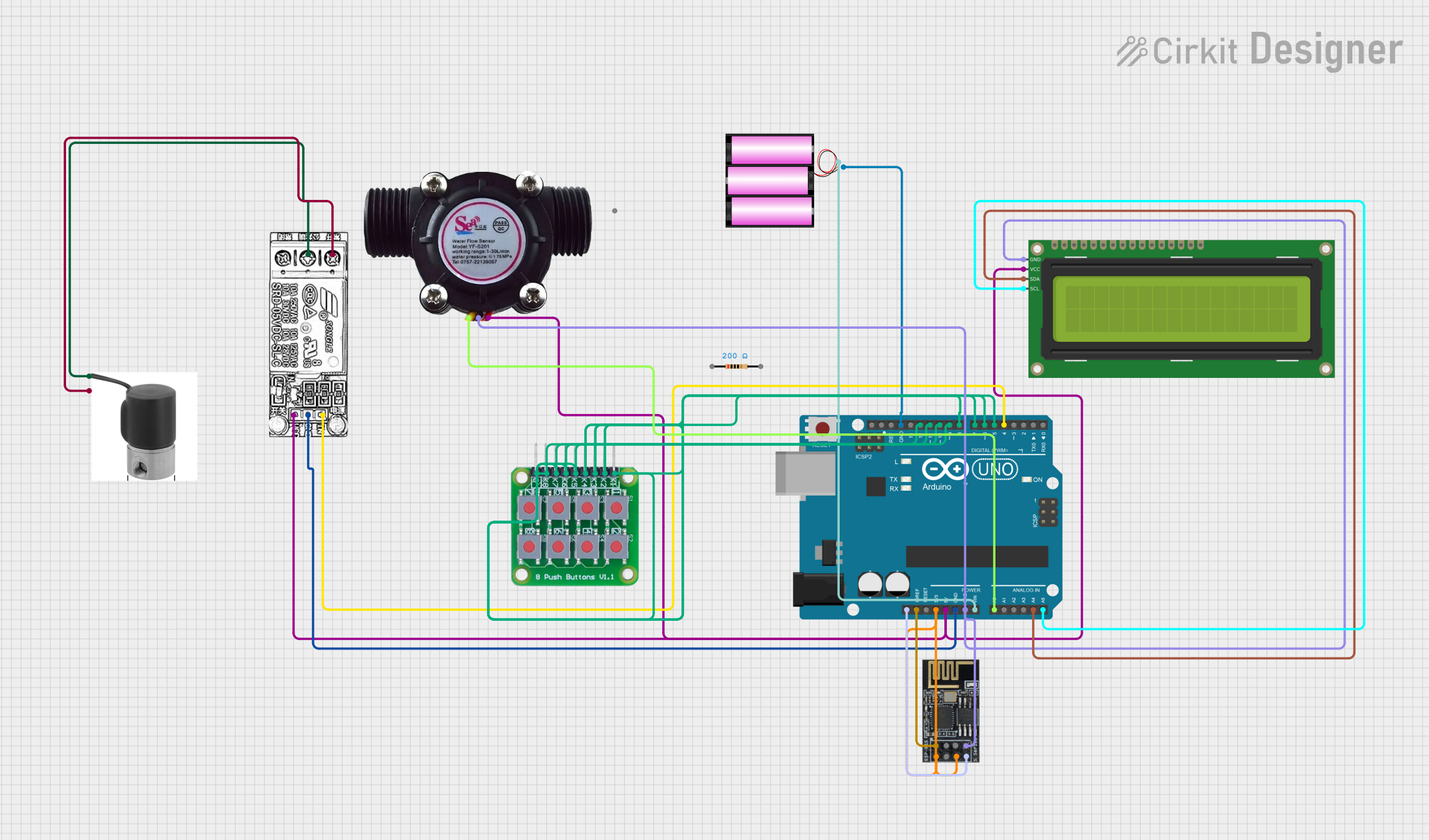
Circuit Documentation
Summary
This circuit is designed to control a water dispensing system using an Arduino UNO microcontroller. The system includes an 8 push button board for selecting water volume, a water flow sensor to measure the dispensed water, a relay module to control a solenoid valve, an ESP8266-01 WiFi module for connectivity, and a 16x2 I2C LCD for displaying information. The system is powered by a 12V battery.
Component List
8 Push Button Board PCB
- Pins: K1, K2, K3, K4, K5, K6, K7, K8, GROUND
- Description: A board with 8 push buttons used to select the volume of water to be dispensed.
Water Flow Sensor
- Pins: Signal, Vcc, GND
- Description: Measures the flow rate of water.
Relay Module
- Pins: NC, COM, INPUT, GND, VCC
- Description: Controls the solenoid valve to start and stop water flow.
Solenoid Valve 12V
- Pins: GND, 12V
- Description: Controls the flow of water.
WiFi Module ESP8266-01
- Pins: RX, GPIO0, GPIO2, GND, +3V3, Reset, CH-PD Chip power down, TX
- Description: Provides WiFi connectivity.
Arduino UNO
- Pins: UNUSED, IOREF, Reset, 3.3V, 5V, GND, Vin, A0, A1, A2, A3, A4, A5, SCL, SDA, AREF, D13, D12, D11, D10, D9, D8, D7, D6, D5, D4, D3, D2, D1, D0
- Description: The main microcontroller used to control the system.
16x2 I2C LCD
- Pins: GND, VCC, SDA, SCL
- Description: Displays information to the user.
Battery 12V
- Pins: +, -
- Description: Powers the circuit.
Resistor
- Pins: pin1, pin2
- Description: Provides resistance in the circuit.
- Properties: 200 Ohms
Wiring Details
8 Push Button Board PCB
- K1 to Arduino UNO D5
- K2 to Arduino UNO D6
- K3 to Arduino UNO D7
- K4 to Arduino UNO D8
- K5 to Arduino UNO D9
- K6 to Arduino UNO D10
- K7 to Arduino UNO D11
- K8 to Arduino UNO D12
- GROUND to Arduino UNO GND
Water Flow Sensor
- Signal to Arduino UNO A0
- Vcc to Arduino UNO 5V
- GND to Arduino UNO GND
Relay Module
- NC to Solenoid Valve 12V
- COM to Solenoid Valve GND
- INPUT to Arduino UNO D4
- GND to Arduino UNO GND
- VCC to Arduino UNO 5V
Solenoid Valve 12V
- GND to Relay Module COM
- 12V to Relay Module NC
WiFi Module ESP8266-01
- RX to Arduino UNO IOREF
- TX to Arduino UNO UNUSED
- +3V3 to Arduino UNO 3.3V
- CH-PD Chip power down to Arduino UNO 3.3V
- GND to Arduino UNO GND
Arduino UNO
- Vin to Battery 12V +
- GND to Battery 12V -
16x2 I2C LCD
- VCC to Arduino UNO 5V
- GND to Arduino UNO GND
- SDA to Arduino UNO A4
- SCL to Arduino UNO A5
Battery 12V
- + to Arduino UNO Vin
- - to Arduino UNO GND
Resistor
- pin1 to appropriate circuit point
- pin2 to appropriate circuit point
Code Documentation
#include <LiquidCrystal_I2C.h>

LiquidCrystal_I2C lcd(0x3F, 16, 2);
const int relayPin = 4;
const int flowSensorPin = A0;
const int buttonPins[] = {5, 6, 7, 8, 9, 10, 11, 12};
int watervolume = 0;
int flowSensorValue = 0;

void setup() {
    Serial.begin(9600);
    lcd.begin(16, 2);
    lcd.print("Water Dispense");
    for (int i = 0; i < 8; i++) {
        pinMode(buttonPins[i], INPUT);
    }
    pinMode(relayPin, OUTPUT);
    digitalWrite(relayPin, LOW);
    pinMode(flowSensorPin, INPUT);
}

void loop() {
    for (int i = 0; i < 8; i++) {
        if (digitalRead(buttonPins[i]) == HIGH) {
            watervolume = (i + 1) * 100;
            lcd.clear();
            lcd.print("Dispensing:");
            lcd.print(watervolume);
            lcd.print("ml");
            break;
        }
    }
    digitalWrite(relayPin, HIGH);
    flowSensorValue = analogRead(flowSensorPin);
    delay(500);
    if (flowSensorValue >= watervolume) {
        digitalWrite(relayPin, LOW);
        lcd.clear();
        lcd.print("Water Dispensed");
    }
    delay(1000);
}
This code initializes the LCD, sets up the pins for the buttons, relay, and flow sensor, and continuously checks for button presses to determine the volume of water to dispense. The relay is activated to start the water flow, and the flow sensor value is monitored to stop the flow once the desired volume is reached.