
Arduino UNO Based Air Quality Monitor with DHT11 and MQ-135 Sensors
View and Edit Project In Cirkit Designer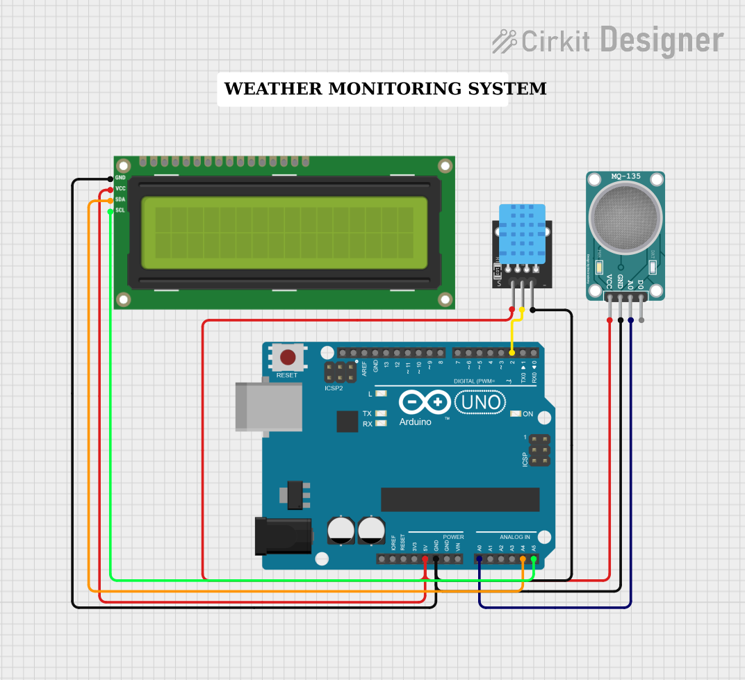
Circuit Documentation
Summary
This circuit is designed to monitor air quality by measuring temperature, humidity, and air composition. It utilizes an Arduino UNO as the central microcontroller to interface with a DHT11 temperature and humidity sensor (KY-015), an MQ-135 air quality sensor, and an I2C LCD 16x2 screen for displaying the measurements. The Arduino UNO reads the sensor data and outputs the information to both the LCD screen and the Serial Monitor for real-time monitoring.
Component List
Arduino UNO
- Description: A microcontroller board based on the ATmega328P.
- Purpose: Acts as the central processing unit for the circuit, reading sensor data and controlling the LCD display.
KY-015 DHT11 Temperature and Humidity Sensor
- Description: A basic, ultra-low-cost digital temperature and humidity sensor.
- Purpose: Measures the ambient temperature and humidity.
MQ-135 Air Quality Sensor
- Description: A sensor for detecting a wide range of gases, including NH3, NOx, alcohol, benzene, smoke, and CO2.
- Purpose: Monitors the air quality by measuring the concentration of various gases.
I2C LCD 16x2 Screen
- Description: A 16x2 character LCD display that uses the I2C communication protocol.
- Purpose: Displays the temperature, humidity, and air quality readings.
Wiring Details
Arduino UNO
- 5V: Powers the DHT11 sensor, MQ-135 sensor, and the I2C LCD screen.
- GND: Common ground for the DHT11 sensor, MQ-135 sensor, and the I2C LCD screen.
- A0: Receives the analog output from the MQ-135 air quality sensor.
- A4 (SDA): I2C data line connected to the I2C LCD screen.
- A5 (SCL): I2C clock line connected to the I2C LCD screen.
- D2: Digital input connected to the DHT11 sensor's data pin.
KY-015 DHT11 Temperature and Humidity Sensor
- 5V: Receives power from the Arduino UNO.
- S: Data pin connected to digital pin D2 on the Arduino UNO.
- GND: Connected to the common ground.
MQ-135 Air Quality Sensor
- VCC: Receives power from the Arduino UNO's 5V output.
- GND: Connected to the common ground.
- A0: Analog output connected to analog pin A0 on the Arduino UNO.
I2C LCD 16x2 Screen
- VCC (5V): Receives power from the Arduino UNO's 5V output.
- GND: Connected to the common ground.
- SDA: I2C data line connected to analog pin A4 on the Arduino UNO.
- SCL: I2C clock line connected to analog pin A5 on the Arduino UNO.
Documented Code
#include <DHT.h>
#include <Wire.h>
#include <LiquidCrystal_I2C.h>

#define DHTPIN 2        // DHT11 data pin
#define DHTTYPE DHT11   // DHT 11
DHT dht(DHTPIN, DHTTYPE);

LiquidCrystal_I2C lcd(0x27, 16, 2); // Change address if necessary
const int MQ135_PIN = A0; // MQ135 analog pin

void setup() {
  Serial.begin(9600);
  dht.begin();
  lcd.begin();
  lcd.backlight();
  lcd.print("Air Quality Monitor");
  delay(2000);
  lcd.clear();
}

void loop() {
  // Read humidity and temperature
  float h = dht.readHumidity();
  float t = dht.readTemperature(); // Temperature in Celsius

  // Read air quality from MQ135
  int airQuality = analogRead(MQ135_PIN);

  // Display data on LCD
  lcd.setCursor(0, 0);
  lcd.print("Temp: ");
  lcd.print(t);
  lcd.print("C");

  lcd.setCursor(0, 1);
  lcd.print("Air Q: ");
  lcd.print(airQuality); // Raw value, consider calibrating it for real values

  // Print to Serial Monitor for debugging
  Serial.print("Humidity: ");
  Serial.print(h);
  Serial.print("%  Temperature: ");
  Serial.print(t);
  Serial.print("C  Air Quality: ");
  Serial.println(airQuality);

  delay(2000); // Update every 2 seconds
}
This code is responsible for initializing the sensors and the LCD screen, reading the sensor data, and displaying the information on the LCD as well as outputting it to the Serial Monitor. The DHT11 sensor is read using the DHT library, and the MQ-135 sensor's analog value is read directly from the analog pin. The I2C LCD screen is controlled using the LiquidCrystal_I2C library. The code includes a delay to update the readings every two seconds.