
ESP32-Controlled Smart Irrigation and Climate Monitoring System
View and Edit Project In Cirkit Designer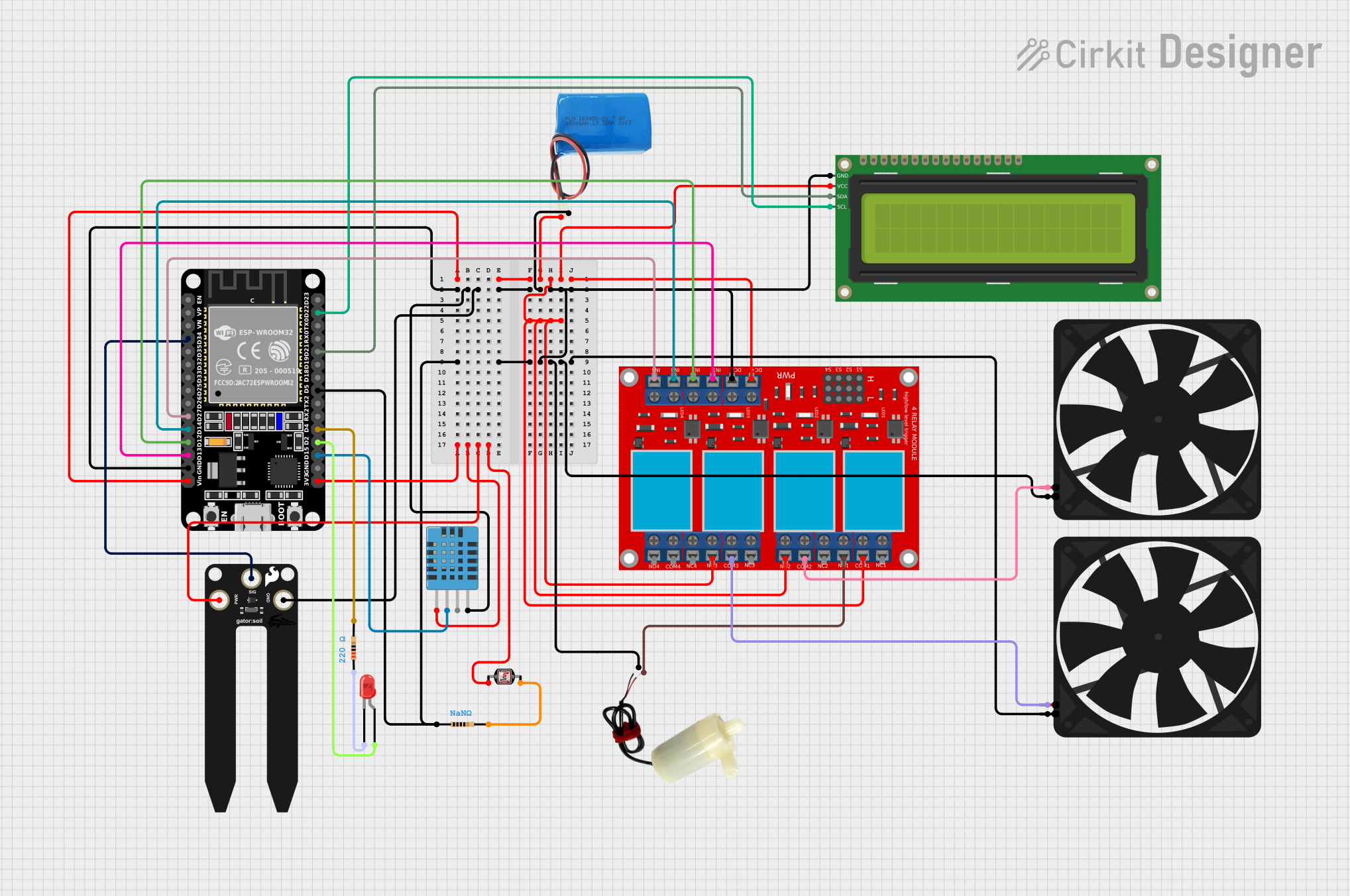
Circuit Documentation
Summary
The circuit in question is designed to control various devices such as a mini water pump, fans, and an LED, as well as to monitor environmental conditions using a DHT11 humidity and temperature sensor and a SparkFun gator:soil moisture sensor. The circuit's brain is an ESP32 microcontroller, which interfaces with a 16x2 I2C LCD for display purposes. The circuit is powered by a 5V battery and includes a 4-channel relay module to control high-power devices. Sensing elements include a photocell (LDR) for light detection. The circuit is designed for applications that require environmental monitoring and control, such as a smart greenhouse or home automation system.
Component List
- 4 Channel Relay Module: Used to control high power or high voltage devices such as the mini water pump and fans.
- 5V Mini Water Pump: A small pump for moving water, controlled by the relay module.
- Fan: Used for air circulation or cooling, controlled by the relay module.
- LED (Red, Two Pin): A simple indicator light.
- DHT11 Humidity and Temperature Sensor: Measures ambient temperature and humidity.
- SparkFun gator:soil: A soil moisture sensor for detecting the water content in soil.
- 16x2 I2C LCD: A display for showing information such as temperature, humidity, and soil moisture levels.
- ESP32 (30 Pin): The microcontroller unit (MCU) that controls the circuit and processes sensor data.
- 5V Battery: Provides power to the circuit.
- Resistor (220 Ohms): Limits current to the LED.
- Photocell (LDR): A light sensor that changes resistance based on light intensity.
- Resistor (NaN Ohms): This component has an unspecified resistance value and its purpose in the circuit is unclear without further information.
Wiring Details
4 Channel Relay Module
- VCC+: Connected to the positive terminal of the 5V battery.
- VCC- (GND): Connected to the negative terminal of the 5V battery.
- COM 1: Connected to the positive terminal of the 5V battery.
- N.O. 1: Connected to the positive pin of the mini water pump.
- COM 2: Connected to the 5V pin of Fan 2.
- N.O. 2: Not connected.
- COM 3: Connected to the 5V pin of Fan 1.
- N.O. 3: Not connected.
- IN 1 - IN 4: Controlled by ESP32 pins D13, D12, D14, and D27 respectively.
5V Mini Water Pump
- Positive Pin: Connected to N.O. 1 on the relay module.
- Negative Pin: Connected to the negative terminal of the 5V battery.
Fan
- 5V: Connected to COM 2 or COM 3 on the relay module (for Fan 1 and Fan 2 respectively).
- GND: Connected to the negative terminal of the 5V battery.
LED (Red, Two Pin)
- Anode: Connected to pin D2 of the ESP32.
- Cathode: Connected to one pin of the 220 Ohm resistor, whose other pin is connected to GND.
DHT11 Humidity and Temperature Sensor
- VDD: Connected to the 3V3 pin of the ESP32.
- DATA: Connected to pin D15 of the ESP32.
- GND: Connected to the negative terminal of the 5V battery.
SparkFun gator:soil
- VCC: Connected to the 3V3 pin of the ESP32.
- GND: Connected to the negative terminal of the 5V battery.
- SIG: Connected to pin D34 of the ESP32.
16x2 I2C LCD
- VCC: Connected to the positive terminal of the 5V battery.
- GND: Connected to the negative terminal of the 5V battery.
- SDA: Connected to pin D21 of the ESP32.
- SCL: Connected to pin D22 of the ESP32.
ESP32 (30 Pin)
- Vin: Connected to the positive terminal of the 5V battery.
- GND: Connected to the negative terminal of the 5V battery.
- 3V3: Powers the DHT11 sensor and the SparkFun gator:soil sensor.
- D2, D4, D12, D13, D14, D15, D21, D22, D27, D34: Various control and data pins connected to other components in the circuit.
5V Battery
- Positive: Provides power to the circuit.
- Negative: Common ground for the circuit.
Resistor (220 Ohms)
- Pin1: Connected to the cathode of the LED.
- Pin2: Connected to the negative terminal of the 5V battery.
Photocell (LDR)
- Pin 0: Connected to the 3V3 pin of the ESP32.
- Pin 1: Connected to a resistor (value unspecified), which is then connected to GND.
Documented Code
There is no code provided for the microcontroller. The documentation of the code would typically include details on how the ESP32 is programmed to interact with the sensors, control the relay module, and display data on the LCD. This would involve setting up the GPIO pins, reading sensor values, controlling relay states, and updating the display. Without the code, we cannot provide further details on the software aspect of this circuit.