
ESP32-Based Solar Power Monitoring System with MPPT and INA219
View and Edit Project In Cirkit Designer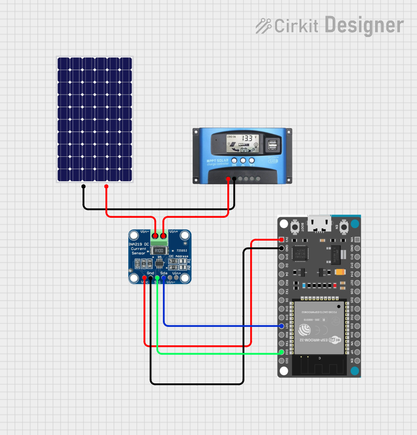
Solar Power Monitoring Circuit Documentation
Summary
This circuit is designed to monitor the voltage and current of a solar power system. It consists of an ESP32 Devkit V1 microcontroller interfaced with an INA219 current sensor to measure the power characteristics of a solar panel. The solar panel is connected to an MPPT (Maximum Power Point Tracking) Solar Charge Controller (SCC), which optimizes the power output from the solar panel and charges a battery or powers a load.
Component List
ESP32 Devkit V1
- Description: A microcontroller development board based on the ESP32 chip, featuring Wi-Fi and Bluetooth connectivity.
- Purpose: Acts as the central processing unit of the circuit, reads sensor data, and communicates information.
INA219
- Description: A high-side current shunt and power monitor with an I2C interface.
- Purpose: Measures the voltage across and current through the solar panel.
MPPT SCC
- Description: A charge controller that uses MPPT technology to extract the maximum power from the solar panel.
- Purpose: Regulates the charging of the battery and the power supply to the load.
Solar Panel
- Description: A photovoltaic panel that converts sunlight into electrical energy.
- Purpose: Provides the primary source of power for the circuit.
Wiring Details
ESP32 Devkit V1
3V3connected to INA219VCCGNDconnected to INA219GNDD22connected to INA219SCLD21connected to INA219SDA
INA219
VCCconnected to ESP32 Devkit V13V3GNDconnected to ESP32 Devkit V1GNDSCLconnected to ESP32 Devkit V1D22SDAconnected to ESP32 Devkit V1D21VIN -connected to Solar Panel-VIN +connected to MPPT SCCSOLAR+
MPPT SCC
SOLAR+connected to INA219VIN +SOLAR-connected to Solar Panel+
Solar Panel
+connected to MPPT SCCSOLAR--connected to INA219VIN -
Documented Code
sketch.ino
#include <Wire.h>
#include <Adafruit_INA219.h>

Adafruit_INA219 ina219;

void setup(void)
{
  Serial.begin(115200);
  while (!Serial) {
      // will pause Zero, Leonardo, etc until serial console opens
      delay(1);
  }

  Serial.println("Hello!");

  // Initialize the INA219.
  // By default the initialization will use the largest range (32V, 2A).  However
  // you can call a setCalibration function to change this range (see comments).
  if (! ina219.begin()) {
    Serial.println("Failed to find INA219 chip");
    while (1) { delay(10); }
  }
  // To use a slightly lower 32V, 1A range (higher precision on amps):
  //ina219.setCalibration_32V_1A();
  // Or to use a lower 16V, 400mA range (higher precision on volts and amps):
  //ina219.setCalibration_16V_400mA();

  Serial.println("Measuring voltage and current with INA219 ...");
}

void loop(void)
{
  float shuntvoltage = 0;
  float busvoltage = 0;
  float current_mA = 0;
  float loadvoltage = 0;
  float power_mW = 0;

  shuntvoltage = ina219.getShuntVoltage_mV();
  busvoltage = ina219.getBusVoltage_V();
  current_mA = ina219.getCurrent_mA();
  power_mW = ina219.getPower_mW();
  loadvoltage = busvoltage + (shuntvoltage / 1000);

  Serial.print("Bus Voltage:   "); Serial.print(busvoltage); Serial.println(" V");
  Serial.print("Shunt Voltage: "); Serial.print(shuntvoltage); Serial.println(" mV");
  Serial.print("Load Voltage:  "); Serial.print(loadvoltage); Serial.println(" V");
  Serial.print("Current:       "); Serial.print(current_mA); Serial.println(" mA");
  Serial.print("Power:         "); Serial.print(power_mW); Serial.println(" mW");
  Serial.println("");

  delay(2000);
}
This code initializes the INA219 sensor and continuously reads and prints the shunt voltage, bus voltage, load voltage, current, and power to the serial monitor every 2 seconds. The ESP32 Devkit V1 is used to communicate with the INA219 sensor via I2C, with the SCL and SDA lines connected to pins D22 and D21, respectively. The INA219 is powered by the 3.3V output from the ESP32. The sensor measures the voltage and current of the solar panel, which is connected to the MPPT SCC.