
Arduino UNO-Based Environmental Monitoring Station with Real-Time Clock and Display
View and Edit Project In Cirkit Designer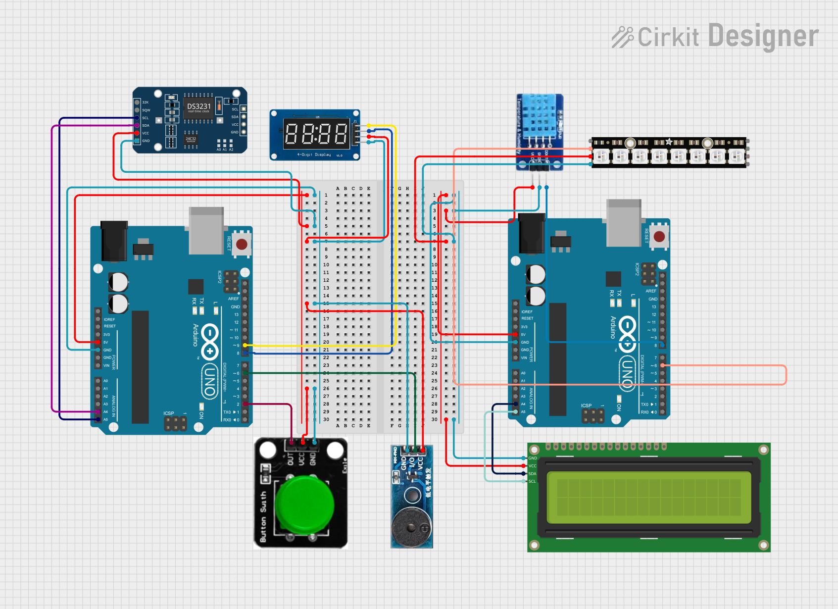
Circuit Documentation
Summary
This document provides a detailed overview of a circuit that includes an Arduino UNO microcontroller, a TM1637 4-digit 7-segment display, a DS3231 Real Time Clock (RTC) module, a 16x2 I2C LCD, a DHT11 temperature and humidity sensor, a buzzer module, a green button, and an Adafruit NeoPixel Stick. The circuit is designed to interface various sensors and output devices with the Arduino UNO, which acts as the central processing unit. The components are interconnected through a series of electrical nets, providing power, ground, and data communication lines.
Component List
Arduino UNO
- Microcontroller board based on the ATmega328P
- Features digital I/O pins, analog input pins, and various power pins
TM1637
- 4-digit 7-segment display module with clock and data interface pins
DS3231 RTC
- Highly accurate I2C real-time clock with an integrated temperature-compensated crystal oscillator (TCXO) and crystal
16x2 I2C LCD
- Alphanumeric liquid crystal display with an I2C interface for displaying text
DHT11
- Basic, low-cost digital temperature and humidity sensor
Buzzer Module
- Electronic buzzer for producing sound signals
Green Button
- Simple push button with an output signal
Adafruit NeoPixel Stick
- 8 individually addressable RGB LEDs, commonly used for LED lighting effects
Wiring Details
Arduino UNO
- Provides 5V and GND to power the DS3231 RTC, TM1637, buzzer module, and green button
- A4 (SDA) and A5 (SCL) are used for I2C communication with the DS3231 RTC and 16x2 I2C LCD
- D9 and D8 are connected to the CLK and DIO pins of the TM1637 respectively
- D6 is connected to the I/O pin of the buzzer module
- D2 is connected to the OUT pin of the green button
TM1637
- CLK and DIO pins are connected to D9 and D8 on the Arduino UNO for data communication
- Powered by 5V and GND from the Arduino UNO
DS3231 RTC
- SDA and SCL pins are connected to A4 and A5 on the Arduino UNO for I2C communication
- Powered by 5V and GND from the Arduino UNO
16x2 I2C LCD
- SDA and SCL pins are connected to A4 and A5 on the Arduino UNO for I2C communication
- Powered by 5V and GND from the Arduino UNO
DHT11
- DATA pin is connected to D8 on the Arduino UNO for data communication
- Powered by 5V and GND from the Arduino UNO
Buzzer Module
- I/O pin is connected to D6 on the Arduino UNO for signal control
- Powered by 5V and GND from the Arduino UNO
Green Button
- OUT pin is connected to D2 on the Arduino UNO to detect button presses
- Powered by 5V and GND from the Arduino UNO
Adafruit NeoPixel Stick
- DATAIN pin is connected to D6 on the Arduino UNO for data communication
- Powered by 5V and GND from the Arduino UNO
Documented Code
Arduino UNO (Primary Microcontroller)
void setup() {
  // put your setup code here, to run once:

}

void loop() {
  // put your main code here, to run repeatedly:

}
Arduino UNO (Secondary Microcontroller)
void setup() {
  // put your setup code here, to run once:

}

void loop() {
  // put your main code here, to run repeatedly:

}
Note: The actual functionality of the code is not provided in the input and should be implemented according to the specific requirements of the circuit's intended operation.