
Arduino UNO and ZMPT101B-Based AC Voltage Monitor with I2C LCD Display
View and Edit Project In Cirkit Designer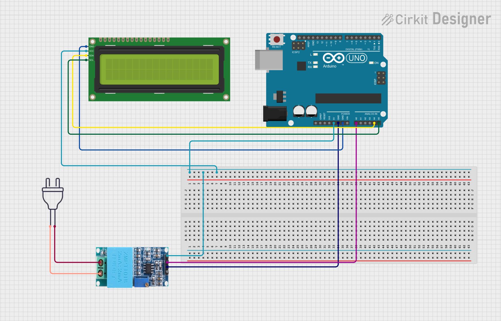
Circuit Documentation
Summary
This circuit is designed to measure and display the AC voltage using a ZMPT101B voltage sensor and an Arduino UNO. The measured voltage is displayed on a 16x2 I2C LCD, and a buzzer is activated if the voltage goes out of a specified range. The circuit is powered by a 220V AC power source.
Component List
ZMPT101B
- Description: Voltage sensor module used to measure AC voltage.
- Pins: OUT, GND, VCC, NEUTRO, FASE
Arduino UNO
- Description: Microcontroller board based on the ATmega328P.
- Pins: UNUSED, IOREF, Reset, 3.3V, 5V, GND, Vin, A0, A1, A2, A3, A4, A5, SCL, SDA, AREF, D13, D12, D11, D10, D9, D8, D7, D6, D5, D4, D3, D2, D1, D0
16x2 I2C LCD
- Description: LCD display module with I2C interface.
- Pins: GND, VCC, SDA, SCL
Power 220V
- Description: 220V AC power source.
- Pins: hot wire, neutral wire
Wiring Details
ZMPT101B
- VCC: Connected to 5V on Arduino UNO
- GND: Connected to GND on Arduino UNO
- OUT: Connected to A0 on Arduino UNO
- NEUTRO: Connected to neutral wire of Power 220V
- FASE: Connected to hot wire of Power 220V
Arduino UNO
- 5V: Connected to VCC on ZMPT101B and VCC on 16x2 I2C LCD
- GND: Connected to GND on ZMPT101B and GND on 16x2 I2C LCD
- A0: Connected to OUT on ZMPT101B
- A4: Connected to SDA on 16x2 I2C LCD
- A5: Connected to SCL on 16x2 I2C LCD
16x2 I2C LCD
- VCC: Connected to 5V on Arduino UNO
- GND: Connected to GND on Arduino UNO
- SDA: Connected to A4 on Arduino UNO
- SCL: Connected to A5 on Arduino UNO
Power 220V
- neutral wire: Connected to NEUTRO on ZMPT101B
- hot wire: Connected to FASE on ZMPT101B
Code Documentation
#include <Wire.h>
#include <LiquidCrystal_I2C.h>

// Create an LCD object. Adjust the address (0x27 or 0x3F) based on your module.
LiquidCrystal_I2C lcd(0x27, 16, 2);

const int voltagePin = A0; // ZMPT101B output connected to A0
const int buzzerPin = 8;   // Buzzer connected to digital pin 8

// Voltage thresholds
const float voltageHighThreshold = 250.0; // High voltage limit (in volts)
const float voltageLowThreshold = 180.0;  // Low voltage limit (in volts)

// Calibration factor for ZMPT101B
const float calibrationFactor = 110.0;

// Voltage detection threshold
const float detectionThreshold = 10.0; // Voltage (in volts) to detect live AC

void setup() {
  pinMode(buzzerPin, OUTPUT);
  digitalWrite(buzzerPin, LOW); // Start with buzzer off
  lcd.init();                   // Initialize the LCD
  lcd.backlight();              // Turn on LCD backlight
  Serial.begin(9600);

  // Display initial message
  lcd.setCursor(0, 0);
  lcd.print("Voltage: 0V");
  lcd.setCursor(0, 1);
  lcd.print("Waiting for AC...");
}

void loop() {
  // Measure RMS voltage
  float rmsVoltage = measureRMSVoltage();

  // Measure instantaneous AC voltage
  float acVoltage = measureACVoltage();

  // Check if AC voltage is detected
  if (rmsVoltage > detectionThreshold) {
    // Display live voltage
    lcd.setCursor(0, 0);
    lcd.print("AC: ");
    lcd.print(acVoltage, 1);  // Display AC voltage
    lcd.print("V    ");       // Clear remaining characters

    lcd.setCursor(0, 1);
    lcd.print("RMS: ");
    lcd.print(rmsVoltage, 1); // Display RMS voltage
    lcd.print("V    ");       // Clear remaining characters

    // Check voltage thresholds and activate buzzer if out of range
    if (rmsVoltage > voltageHighThreshold || rmsVoltage < voltageLowThreshold) {
      digitalWrite(buzzerPin, HIGH); // Turn on buzzer
      Serial.println("Voltage out of range! Buzzer activated.");
    } else {
      digitalWrite(buzzerPin, LOW); // Turn off buzzer
    }
  } else {
    // If no significant voltage is detected, display "Waiting for AC"
    lcd.setCursor(0, 0);
    lcd.print("Voltage: 0V   "); // Show "0V" when no AC is detected
    lcd.setCursor(0, 1);
    lcd.print("Waiting for AC...");
    digitalWrite(buzzerPin, LOW); // Ensure buzzer is off
  }

  delay(500); // Wait before next reading
}

// Function to measure RMS voltage using ZMPT101B
float measureRMSVoltage() {
  const int sampleCount = 500; // Number of samples for RMS calculation
  float sum = 0.0;

  // Collect multiple samples
  for (int i = 0; i < sampleCount; i++) {
    int rawValue = analogRead(voltagePin);
    float voltage = (rawValue / 1023.0) * 5.0; // Convert to actual voltage (5V reference)
    float centeredVoltage = voltage - 2.5;    // Remove DC offset
    sum += centeredVoltage * centeredVoltage;
    delay(1); // Small delay for stability
  }

  // Calculate RMS
  float meanSquare = sum / sampleCount;
  float rmsVoltage = sqrt(meanSquare) * calibrationFactor;
  return rmsVoltage;
}

// Function to measure instantaneous AC voltage (waveform)
float measureACVoltage() {
  int rawValue = analogRead(voltagePin);
  float voltage = (rawValue / 1023.0) * 5.0; // Convert to actual voltage (5V reference)
  return voltage * calibrationFactor;       // Scale by calibration factor
}
This code initializes the LCD and sets up the pins for the voltage sensor and buzzer. It continuously measures the RMS and instantaneous AC voltage, displays the values on the LCD, and activates the buzzer if the voltage is out of the specified range.