
Circuit Documentation
Summary of the Circuit
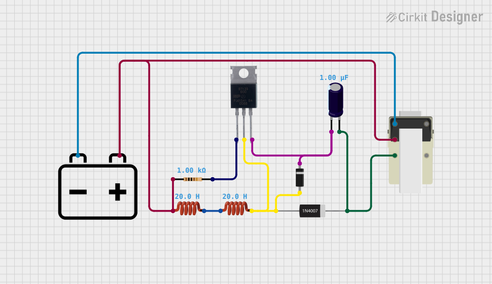
This circuit appears to be a power supply circuit with regulation and protection features. It includes a transformer for stepping down voltage, a rectifier diode for converting AC to DC, a Zener diode for voltage regulation, an electrolytic capacitor for smoothing out ripples in the DC output, and a BT139 600 triac for controlling power flow. The inductors may be used for filtering or energy storage, and the resistor could be setting the biasing for the Zener diode or limiting current. The 12v battery may serve as a backup power source or for providing a reference voltage.
Component List
Inductor
- Description: A passive two-terminal electrical component that stores energy in a magnetic field when electric current flows through it.
- Properties: Inductance - 20 Henrys
12v Battery
- Description: A power source that provides a voltage of 12 volts.
- Properties: N/A
Resistor
- Description: A passive two-terminal electrical component that implements electrical resistance as a circuit element.
- Properties: Resistance - 1000 Ohms
Zener Diode
- Description: A type of diode that allows current to flow in the forward direction like a normal diode, but also in the reverse direction if the voltage is larger than the breakdown voltage known as "Zener knee voltage".
- Properties: N/A
1N4007 Rectifier Diode
- Description: A common rectifier diode, often used in power supplies for converting AC to DC.
- Properties: N/A
BT139 600
- Description: A triac, which is a three-terminal electronic component that can conduct current in either direction when it is triggered.
- Properties: N/A
Electrolytic Capacitor
- Description: A type of capacitor that uses an electrolyte to achieve a larger capacitance than other capacitor types.
- Properties: Capacitance - 1 microfarad
Transformer
- Description: An electrical device that transfers electrical energy between two or more circuits through electromagnetic induction.
- Properties: N/A
Wiring Details
Inductor
- Pin 0 is connected to the positive terminal of the 12v Battery and pin 1 of another Inductor.
- Pin 1 is connected to the anode of the Zener Diode and MT2 of the BT139 600.
12v Battery
- Positive terminal is connected to pin 0 of an Inductor and pin 4 of the Transformer.
- Negative terminal is connected to pin 3 of the Transformer.
Resistor
- Pin 1 is connected to pin 4 of the Transformer, the positive terminal of the 12v Battery, and pin 0 of an Inductor.
- Pin 2 is connected to MT1 of the BT139 600.
Zener Diode
- Cathode is connected to the negative terminal of the Electrolytic Capacitor and GATE of the BT139 600.
- Anode is connected to the anode of the 1N4007 Rectifier Diode, pin 1 of an Inductor, and MT2 of the BT139 600.
1N4007 Rectifier Diode
- Cathode is connected to the positive terminal of the Electrolytic Capacitor.
- Anode is connected to the anode of the Zener Diode, pin 1 of an Inductor, and MT2 of the BT139 600.
BT139 600
- MT1 is connected to pin 2 of the Resistor.
- MT2 is connected to the anode of the Zener Diode, the anode of the 1N4007 Rectifier Diode, and pin 1 of an Inductor.
- GATE is connected to the negative terminal of the Electrolytic Capacitor and the cathode of the Zener Diode.
Electrolytic Capacitor
- Negative terminal is connected to the cathode of the Zener Diode and GATE of the BT139 600.
- Positive terminal is connected to pin 5 of the Transformer and the cathode of the 1N4007 Rectifier Diode.
Transformer
- Pin 4 is connected to pin 1 of the Resistor and the positive terminal of the 12v Battery.
- Pin 3 is connected to the negative terminal of the 12v Battery.
- Pin 5 is connected to the positive terminal of the Electrolytic Capacitor.
Documented Code
There is no code provided for any microcontrollers in the circuit. If code becomes available, it should be documented in this section with appropriate comments and explanations for each function and routine.