ESP32-Based Obstacle Avoidance Robot with Ultrasonic and IR Sensors
Circuit Documentation
Summary
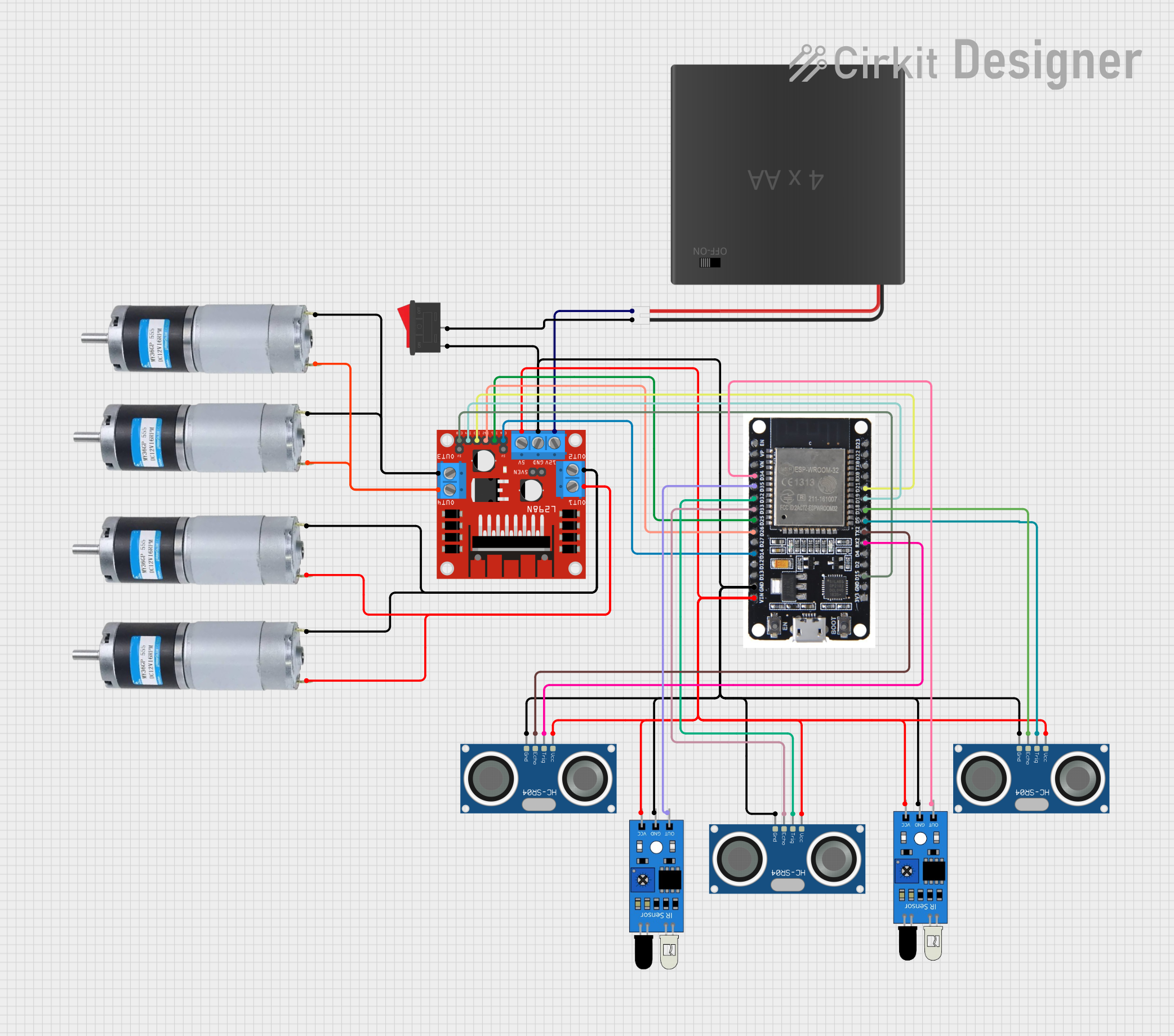
This document provides a detailed overview of a circuit that includes various sensors, a motor driver, a microcontroller, and other components. The circuit is designed to interface multiple sensors with an ESP32 microcontroller and control DC motors using an L298N motor driver. The power supply is provided by a 4xAA battery pack, and a rocker switch is used to control the power.
Component List
HC-SR04 Ultrasonic Sensor
- Pins: VCC, TRIG, ECHO, GND
- Description: Ultrasonic distance sensor used for measuring distance.
- Purpose: Distance measurement.
IR Sensor
- Pins: out, gnd, vcc
- Description: Infrared sensor used for object detection.
- Purpose: Object detection.
L298N DC Motor Driver
- Pins: OUT1, OUT2, 12V, GND, 5V, OUT3, OUT4, 5V-ENA-JMP-I, 5V-ENA-JMP-O, +5V-J1, +5V-J2, ENA, IN1, IN2, IN3, IN4, ENB
- Description: Dual H-Bridge motor driver used to control DC motors.
- Purpose: Motor control.
ESP32
- Pins: EN, VP, VN, D34, D35, D32, D33, D25, D26, D27, D14, D12, D13, GND, VIN, 3V3, D15, D2, D4, RX2, TX2, D5, D18, D19, D21, RX0, TX0, D22, D23, BOOT
- Description: Microcontroller with Wi-Fi and Bluetooth capabilities.
- Purpose: Central control unit.
DC Motor
- Pins: positive, negative
- Description: DC motor used for mechanical movement.
- Purpose: Actuation.
Rocker Switch
- Pins: 1, 2
- Description: Switch used to control the power supply.
- Purpose: Power control.
4xAA Battery Pack
- Pins: POS, NEG
- Description: Battery pack providing power to the circuit.
- Purpose: Power supply.
Wiring Details
HC-SR04 Ultrasonic Sensor
- VCC: Connected to 5V (L298N DC motor driver)
- TRIG: Connected to D32 (ESP32)
- ECHO: Connected to D33 (ESP32)
- GND: Connected to GND (Common ground)
HC-SR04 Ultrasonic Sensor
- VCC: Connected to 5V (L298N DC motor driver)
- TRIG: Connected to D5 (ESP32)
- ECHO: Connected to D18 (ESP32)
- GND: Connected to GND (Common ground)
HC-SR04 Ultrasonic Sensor
- VCC: Connected to 5V (L298N DC motor driver)
- TRIG: Connected to RX2 (ESP32)
- ECHO: Connected to TX2 (ESP32)
- GND: Connected to GND (Common ground)
IR Sensor
- out: Connected to D34 (ESP32)
- gnd: Connected to GND (Common ground)
- vcc: Connected to 5V (L298N DC motor driver)
IR Sensor
- out: Connected to D35 (ESP32)
- gnd: Connected to GND (Common ground)
- vcc: Connected to 5V (L298N DC motor driver)
L298N DC Motor Driver
- IN1: Connected to D25 (ESP32)
- IN2: Connected to D26 (ESP32)
- ENA: Connected to D14 (ESP32)
- IN3: Connected to D21 (ESP32)
- IN4: Connected to D19 (ESP32)
- ENB: Connected to D15 (ESP32)
- GND: Connected to GND (Common ground)
- 5V: Connected to 5V (Common 5V line)
- 12V: Connected to POS (4xAA Battery Pack)
- OUT1: Connected to positive (DC Motor)
- OUT2: Connected to negative (DC Motor)
- OUT3: Connected to negative (DC Motor)
- OUT4: Connected to positive (DC Motor)
ESP32
- GND: Connected to GND (Common ground)
- VIN: Connected to 5V (Common 5V line)
DC Motor
- positive: Connected to OUT1 (L298N DC motor driver)
- negative: Connected to OUT2 (L298N DC motor driver)
DC Motor
- positive: Connected to OUT1 (L298N DC motor driver)
- negative: Connected to OUT2 (L298N DC motor driver)
DC Motor
- positive: Connected to OUT4 (L298N DC motor driver)
- negative: Connected to OUT3 (L298N DC motor driver)
DC Motor
- positive: Connected to OUT4 (L298N DC motor driver)
- negative: Connected to OUT3 (L298N DC motor driver)
Rocker Switch
- 1: Connected to GND (Common ground)
- 2: Connected to NEG (4xAA Battery Pack)
4xAA Battery Pack
- POS: Connected to 12V (L298N DC motor driver)
- NEG: Connected to 2 (Rocker Switch)
Code
No code is provided for this circuit.
This document provides a comprehensive overview of the circuit, including a summary, component list, wiring details, and code documentation. The wiring details section ensures that each component's connections are clearly outlined, making it easier to understand and replicate the circuit.