
Arduino UNO-Based Ambient Light and IR Object Detection System
View and Edit Project In Cirkit Designer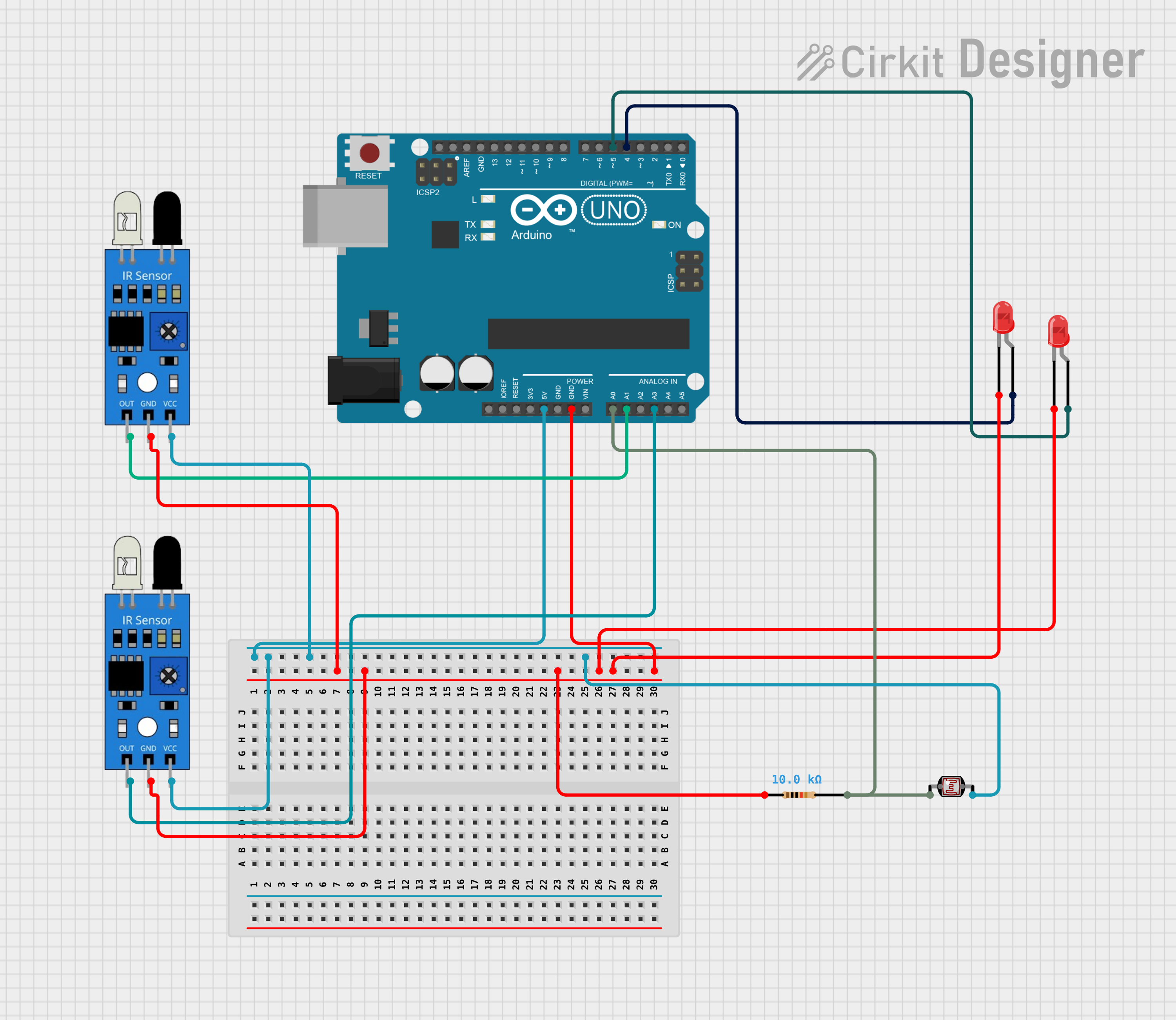
Circuit Documentation
Summary of the Circuit
The circuit in question appears to be a sensor-based system utilizing an Arduino UNO as the central microcontroller. The circuit includes two infrared (IR) sensors, two red LEDs, a photocell (Light Dependent Resistor, LDR), and a resistor. The Arduino UNO is responsible for processing signals from the IR sensors and the photocell, and controlling the LEDs based on the input from these sensors.
Component List
Arduino UNO
- Microcontroller board based on the ATmega328P
- It has 14 digital input/output pins, 6 analog inputs, a 16 MHz quartz crystal, a USB connection, a power jack, an ICSP header, and a reset button.
LED: Two Pin (red)
- A simple red light-emitting diode with an anode and cathode for basic light indication.
IR Sensor
- An infrared sensor capable of detecting infrared light, often used for proximity or object detection.
Resistor
- A passive two-terminal electrical component that implements electrical resistance as a circuit element.
- Resistance: 10,000 Ohms
Photocell (LDR)
- A light-dependent resistor whose resistance decreases with increasing incident light intensity; it can be used as a light sensor.
Wiring Details
Arduino UNO
- 5V: Connected to the VCC of both IR sensors and the anode of the photocell.
- GND: Connected to the ground (GND) of both IR sensors, the cathode of both red LEDs, and one pin of the resistor.
- A0: Connected to one pin of the photocell and one pin of the resistor.
- A1: Connected to the output of one IR sensor.
- A3: Connected to the output of the other IR sensor.
- D4: Connected to the anode of one red LED.
- D5: Connected to the anode of the other red LED.
LED: Two Pin (red)
- Cathode: Connected to the ground (GND) of the circuit.
- Anode: Connected to a digital pin (D4 or D5) of the Arduino UNO.
IR Sensor
- Out: Connected to an analog pin (A1 or A3) of the Arduino UNO.
- GND: Connected to the ground (GND) of the circuit.
- VCC: Connected to the 5V supply from the Arduino UNO.
Resistor
- Pin1: Connected to the ground (GND) of the circuit.
- Pin2: Connected to the anode of the photocell and the A0 pin of the Arduino UNO.
Photocell (LDR)
- Pin 0: Connected to the A0 pin of the Arduino UNO.
- Pin 1: Connected to the 5V supply from the Arduino UNO.
Documented Code
Arduino UNO Code (sketch.ino)
void setup() {
  // put your setup code here, to run once:

}

void loop() {
  // put your main code here, to run repeatedly:

}
Note: The provided code is a template and does not contain any functional code. It needs to be populated with the logic to read sensor data and control the LEDs accordingly.