
Circuit Documentation
Summary of the Circuit
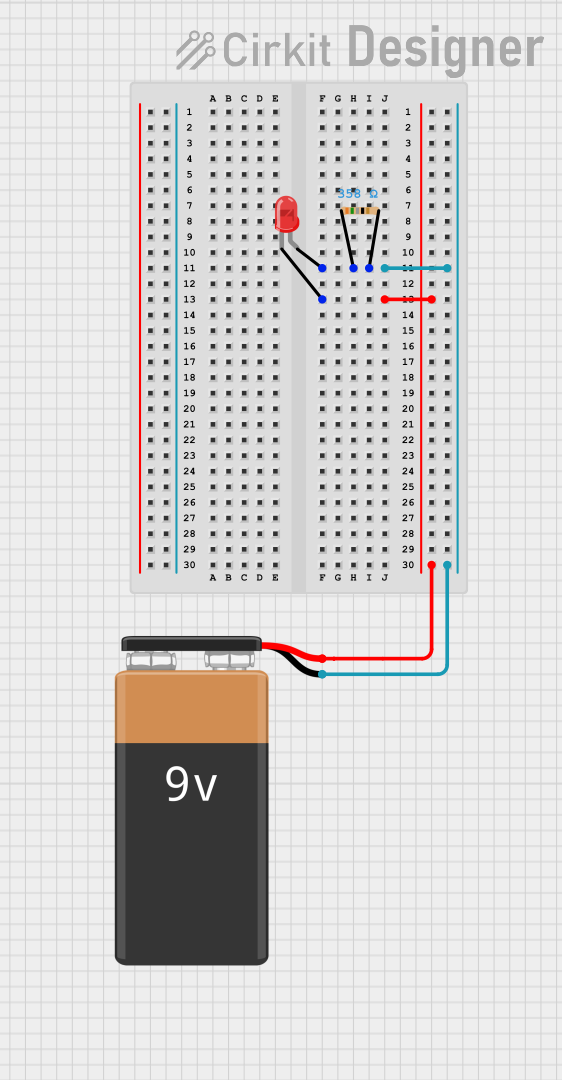
The circuit described by the provided inputs is a simple LED circuit powered by a 9V battery. The circuit includes a single LED, a resistor to limit the current through the LED, and a 9V battery as the power source. The LED has two pins: an anode and a cathode. The anode is connected to one end of the resistor, while the other end of the resistor is connected to the positive terminal of the battery. The cathode of the LED is connected directly to the negative terminal of the battery. This configuration ensures that the LED is properly biased and that the current flowing through it is limited to a safe value by the resistor.
Component List
9V Battery
- Description: A standard 9V battery used as the power source for the circuit.
- Pins: [-, +]
LED: Two Pin (red)
- Description: A red two-pin light-emitting diode (LED) used as the visual indicator in the circuit.
- Pins: [cathode, anode]
Resistor
- Description: A resistor used to limit the current flowing through the LED.
- Pins: [pin1, pin2]
- Properties: Resistance: 358 Ohms
Wiring Details
9V Battery
- Positive Terminal (+): Connected to pin1 of the Resistor.
- Negative Terminal (-): Connected to the cathode of the LED.
LED: Two Pin (red)
- Anode: Connected to pin1 of the Resistor.
- Cathode: Connected to the negative terminal (-) of the 9V Battery.
Resistor
- Pin1: Connected to the anode of the LED and the positive terminal (+) of the 9V Battery.
- Pin2: Connected to the negative terminal (-) of the 9V Battery.
Documented Code
There is no microcontroller or embedded code associated with this circuit as per the provided inputs. Therefore, this section is not applicable to the current circuit documentation.