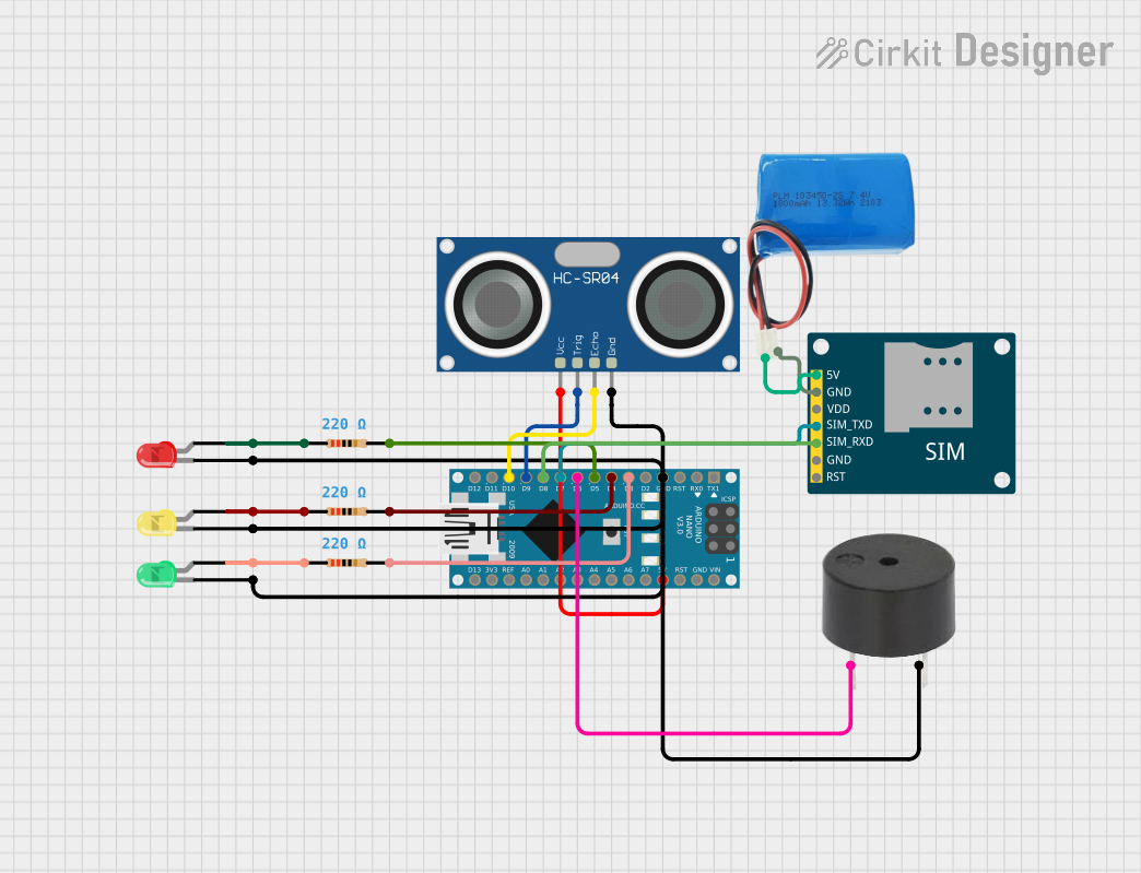
Arduino Nano-Based Flood Alert System with GSM Notifications

Circuit Documentation
Summary
This circuit is designed to monitor water levels using an HC-SR04 Ultrasonic Sensor and provide visual and auditory alerts based on predefined distance thresholds. It utilizes an Arduino Nano as the central microcontroller to process sensor data and control the outputs, which include three LEDs (green, yellow, and red) and a buzzer. The circuit also features a SIM800L GSM Module for sending SMS alerts when certain conditions are met. A 5V battery powers the GSM module, while the Arduino Nano and other components are powered through the Arduino's voltage regulator.
Component List
- Arduino Nano: A compact microcontroller board based on the ATmega328P, featuring digital and analog I/O pins.
- Buzzer: An electromechanical component that produces sound when energized.
- LED (Green): A green light-emitting diode used for indicating safe conditions.
- LED (Yellow): A yellow light-emitting diode used for indicating warning conditions.
- LED (Red): A red light-emitting diode used for indicating danger conditions.
- SIM800L GSM Module: A cellular communication module capable of sending SMS messages.
- Resistor (220 Ohms): Three resistors used to limit current to the LEDs.
- HC-SR04 Ultrasonic Sensor: A sensor used to measure distance via ultrasonic waves.
- 5V Battery: A power source for the GSM module.
Wiring Details
Arduino Nano
- D3: Connected to the anode of the green LED through a 220 Ohm resistor.
- D4: Connected to the anode of the yellow LED through a 220 Ohm resistor.
- D5: Connected to the anode of the red LED through a 220 Ohm resistor.
- D6: Connected to the buzzer.
- D7: Connected to the SIM_TXD pin of the SIM800L GSM Module.
- D8: Connected to the SIM_RXD pin of the SIM800L GSM Module.
- D9: Connected to the TRIG pin of the HC-SR04 Ultrasonic Sensor.
- D10: Connected to the ECHO pin of the HC-SR04 Ultrasonic Sensor.
- 5V: Connected to the VCC pin of the HC-SR04 Ultrasonic Sensor.
- GND: Common ground for the buzzer, HC-SR04 Ultrasonic Sensor, and all LEDs.
Buzzer
- PIN: Connected to D6 on the Arduino Nano.
- GND: Connected to the common ground.
LEDs
- Green LED: Anode connected to D3 on the Arduino Nano through a 220 Ohm resistor. Cathode connected to the common ground.
- Yellow LED: Anode connected to D4 on the Arduino Nano through a 220 Ohm resistor. Cathode connected to the common ground.
- Red LED: Anode connected to D5 on the Arduino Nano through a 220 Ohm resistor. Cathode connected to the common ground.
SIM800L GSM Module
- 5V: Connected to the positive pin of the 5V battery.
- GND: Connected to the negative pin of the 5V battery.
- SIM_TXD: Connected to D7 on the Arduino Nano.
- SIM_RXD: Connected to D8 on the Arduino Nano.
HC-SR04 Ultrasonic Sensor
- VCC: Connected to 5V on the Arduino Nano.
- TRIG: Connected to D9 on the Arduino Nano.
- ECHO: Connected to D10 on the Arduino Nano.
- GND: Connected to the common ground.
Resistor (220 Ohms)
- Three resistors each connected in series with the anode of one LED and a digital pin on the Arduino Nano (D3, D4, D5).
5V Battery
- Positive: Connected to the 5V pin of the SIM800L GSM Module.
- Negative: Connected to the GND pin of the SIM800L GSM Module.
Documented Code
#include <SoftwareSerial.h>

const int trigPin = 9;     // Trig pin for ultrasonic sensor
const int echoPin = 10;    // Echo pin for ultrasonic sensor
const int greenLED = 3;    // Green LED pin
const int yellowLED = 4;   // Yellow LED pin
const int redLED = 5;      // Red LED pin
const int buzzer = 6;      // Buzzer pin

// Define distance thresholds (in cm)
const int safeDistance = 100;      // Safe distance
const int warningDistance = 50;    // Warning distance
const int dangerDistance = 20;     // Danger distance

// GSM module connections
SoftwareSerial gsm(7, 8);  // GSM TX to pin 7, RX to pin 8

void setup() {
  // Pin Modes
  pinMode(trigPin, OUTPUT);
  pinMode(echoPin, INPUT);
  pinMode(greenLED, OUTPUT);
  pinMode(yellowLED, OUTPUT);
  pinMode(redLED, OUTPUT);
  pinMode(buzzer, OUTPUT);

  // Initialize GSM module and Serial for debugging
  gsm.begin(9600);
  Serial.begin(9600);
  delay(1000);  // Allow time for setup
}

void loop() {
  // Variables to hold duration of echo and calculated distance
  long duration, distance;

  // Trigger the ultrasonic sensor to send a pulse
  digitalWrite(trigPin, LOW);
  delayMicroseconds(2);
  digitalWrite(trigPin, HIGH);
  delayMicroseconds(10);
  digitalWrite(trigPin, LOW);

  // Measure the duration of the echo pulse
  duration = pulseIn(echoPin, HIGH);

  // Calculate the distance in centimeters
  distance = (duration * 0.034) / 2;

  // Print the distance for debugging
  Serial.print("Distance: ");
  Serial.print(distance);
  Serial.println(" cm");

  // Flood warning logic based on distance
  if (distance > safeDistance) {
    // Safe condition
    digitalWrite(greenLED, HIGH);
    digitalWrite(yellowLED, LOW);
    digitalWrite(redLED, LOW);
    digitalWrite(buzzer, LOW);
  }
  else if (distance <= safeDistance && distance > warningDistance) {
    // Warning condition
    digitalWrite(greenLED, LOW);
    digitalWrite(yellowLED, HIGH);
    digitalWrite(redLED, LOW);
    digitalWrite(buzzer, LOW);
    sendSMS("Warning! Water level is rising.");
  }
  else if (distance <= warningDistance && distance > dangerDistance) {
    // Danger condition
    digitalWrite(greenLED, LOW);
    digitalWrite(yellowLED, LOW);
    digitalWrite(redLED, HIGH);
    digitalWrite(buzzer, HIGH);
    sendSMS("Danger! Water level has reached a critical point.");
  }

  // Delay for 2 seconds before the next reading
  delay(2000);
}

// Function to send SMS alerts
void sendSMS(String message) {
  gsm.println("AT+CMGF=1");  // Set GSM to text mode
  delay(1000);
  gsm.println("AT+CMGS=\"+91xxxxxxxxxx\"");  // Replace with recipient's phone number
  delay(1000);
  gsm.println(message);  // Send the message
  delay(100);
  gsm.println((char)26);  // ASCII code of CTRL+Z to send SMS
  delay(1000);
}
This code is responsible for reading the distance from the ultrasonic sensor and activating the appropriate LED and buzzer based on the distance thresholds. It also includes functionality to send SMS alerts via the GSM module when the water level reaches warning or danger conditions.