
ESP32-Based Smart Fire and Gas Detection System with Wi-Fi Alerts
View and Edit Project In Cirkit Designer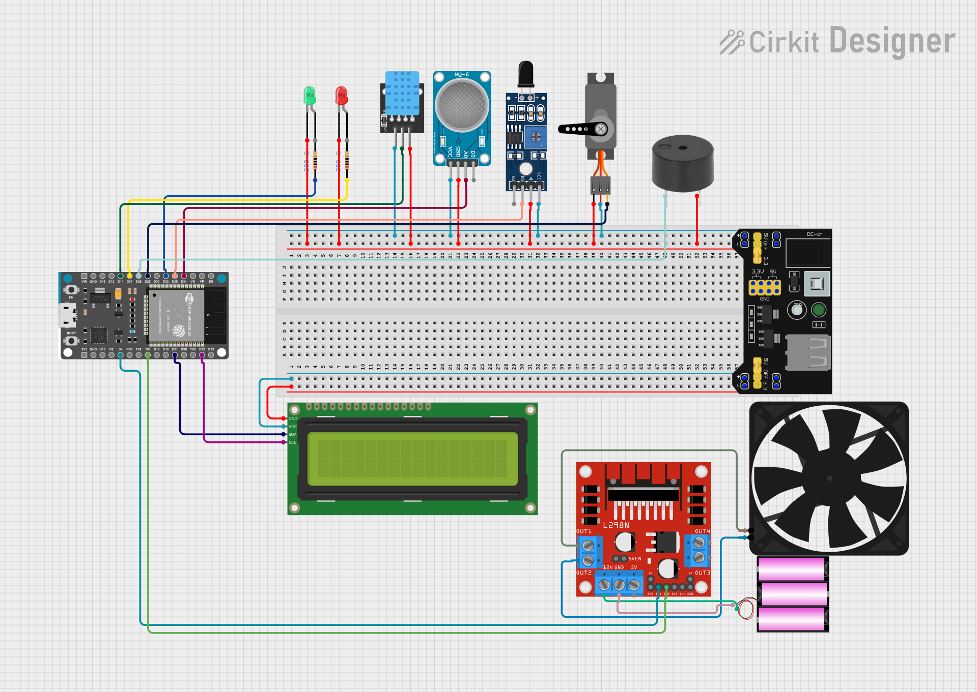
Circuit Documentation
Summary
This circuit is designed to interface an ESP32 microcontroller with various sensors and actuators. It reads temperature and humidity from a DHT11 sensor and displays the values on a 16x2 I2C LCD. It also monitors a flame sensor and an MQ-6 gas sensor. If a flame is detected, it displays a warning on the LCD, sends a message via Telegram, and activates a red LED, servo, buzzer, and fan. If LPG gas is detected, it displays a warning on the LCD, sends a message via Telegram, and activates the same actuators. If no gas is detected, it displays a safe message and activates a green LED.
Component List
ESP32 Devkit V1
- Description: Microcontroller
- Pins: 3V3, GND, D15, D2, D4, RX2, TX2, D5, D18, D19, D21, RX0, TX0, D22, D23, EN, VP, VN, D34, D35, D32, D33, D25, D26, D27, D14, D12, D13, VIN
LED: Two Pin (red)
- Description: Red LED
- Pins: cathode, anode
LED: Two Pin (green)
- Description: Green LED
- Pins: cathode, anode
Resistor
- Description: Resistor
- Pins: pin1, pin2
- Properties: 200 Ohms
16x2 I2C LCD
- Description: LCD Display
- Pins: GND, VCC, SDA, SCL
Buzzer
- Description: Buzzer
- Pins: PIN, GND
Servo
- Description: Servo Motor
- Pins: GND, VCC, PWM
Fan
- Description: Fan
- Pins: GND, 5V
Sensor SHT113 Flame
- Description: Flame Sensor
- Pins: A0, D0, GND, VCC
KY-015 DHT11
- Description: Temperature and Humidity Sensor
- Pins: 5V, S, GND
MB102 Breadboard Power Supply Module 3.3V/5V
- Description: Power Supply Module
- Pins: VCC, GND, 3.3V, 5V
MQ-6 SENSOR LPG GAS
- Description: Gas Sensor
- Pins: VCC, GND, A0, D0
L298N DC motor driver
- Description: Motor Driver
- Pins: OUT1, OUT2, 12V, GND, 5V, OUT3, OUT4, 5V-ENA-JMP-I, 5V-ENA-JMP-O, +5V-J1, +5V-J2, ENA, IN1, IN2, IN3, IN4, ENB
Battery 12V
- Description: Battery
- Pins: +, -
Wiring Details
ESP32 Devkit V1
- D4 to L298N DC motor driver IN1
- D5 to L298N DC motor driver IN2
- D21 to 16x2 I2C LCD SDA
- D22 to 16x2 I2C LCD SCL
- D34 to MQ-6 SENSOR LPG GAS A0
- D35 to Sensor SHT113 Flame D0
- D32 to Resistor pin1
- D25 to Servo PWM
- D26 to Buzzer PIN
- D27 to Resistor pin1
- D14 to KY-015 DHT11 S
LED: Two Pin (red)
- cathode to MB102 Breadboard Power Supply Module GND
LED: Two Pin (green)
- cathode to MB102 Breadboard Power Supply Module GND
Resistor
- pin1 to ESP32 Devkit V1 D32
- pin1 to ESP32 Devkit V1 D27
16x2 I2C LCD
- GND to MB102 Breadboard Power Supply Module GND
- VCC to MB102 Breadboard Power Supply Module VCC
- SDA to ESP32 Devkit V1 D21
- SCL to ESP32 Devkit V1 D22
Buzzer
- PIN to ESP32 Devkit V1 D26
- GND to MB102 Breadboard Power Supply Module GND
Servo
- GND to MB102 Breadboard Power Supply Module GND
- VCC to MB102 Breadboard Power Supply Module VCC
- PWM to ESP32 Devkit V1 D25
Fan
- GND to L298N DC motor driver OUT2
- 5V to L298N DC motor driver OUT1
Sensor SHT113 Flame
- A0 to ESP32 Devkit V1 D35
- D0 to ESP32 Devkit V1 D35
- GND to MB102 Breadboard Power Supply Module GND
- VCC to MB102 Breadboard Power Supply Module VCC
KY-015 DHT11
- 5V to MB102 Breadboard Power Supply Module VCC
- S to ESP32 Devkit V1 D14
- GND to MB102 Breadboard Power Supply Module GND
MB102 Breadboard Power Supply Module 3.3V/5V
- GND to 16x2 I2C LCD GND
- GND to LED: Two Pin (green) cathode
- GND to LED: Two Pin (red) cathode
- GND to KY-015 DHT11 GND
- GND to MQ-6 SENSOR LPG GAS GND
- GND to Sensor SHT113 Flame GND
- GND to Servo GND
- GND to Buzzer GND
- VCC to 16x2 I2C LCD VCC
- VCC to KY-015 DHT11 5V
- VCC to MQ-6 SENSOR LPG GAS VCC
- VCC to Sensor SHT113 Flame VCC
- VCC to Servo VCC
MQ-6 SENSOR LPG GAS
- VCC to MB102 Breadboard Power Supply Module VCC
- GND to MB102 Breadboard Power Supply Module GND
- A0 to ESP32 Devkit V1 D34
L298N DC motor driver
- IN1 to ESP32 Devkit V1 D4
- IN2 to ESP32 Devkit V1 D5
- OUT1 to Fan 5V
- OUT2 to Fan GND
- 12V to Battery 12V +
- GND to Battery 12V -
Battery 12V
- + to L298N DC motor driver 12V
- - to L298N DC motor driver GND
Code Documentation
/*
 * This Arduino sketch is designed for an ESP32 microcontroller to interface with
 * various sensors and actuators. It reads temperature and humidity from a DHT11
 * sensor and displays the values on a 16x2 I2C LCD. It also monitors a flame
 * sensor and an MQ-6 gas sensor. If a flame is detected, it displays a warning
 * on the LCD, sends a message via Telegram, and activates a red LED, servo,
 * buzzer, and fan. If LPG gas is detected, it displays a warning on the LCD,
 * sends a message via Telegram, and activates the same actuators. If no gas is
 * detected, it displays a safe message and activates a green LED.
 */

#include <Wire.h>
#include <LiquidCrystal_I2C.h>
#include <DHT.h>
#include <WiFi.h>
#include <UniversalTelegramBot.h>
#include <Servo.h>

#define DHTPIN 14
#define DHTTYPE DHT11
#define FLAME_PIN 35
#define MQ6_PIN 34
#define RED_LED_PIN 32
#define GREEN_LED_PIN 27
#define BUZZER_PIN 26
#define SERVO_PIN 25
#define FAN_PIN1 4
#define FAN_PIN2 5

const char* ssid = "Airtel_8272878748";//"oplus_co_aqwuon"
const char* password = "air56101";//"ludw6620"
const char* telegramBotToken = "8155996349:AAHqXEu4mk0w2v5VDdPcPK2Ll9oU