
Raspberry Pi Pico W Controlled Multi-Color LED Array with Pushbutton Interaction
View and Edit Project In Cirkit Designer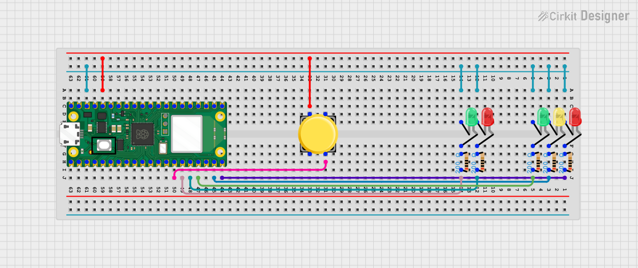
Circuit Documentation
Summary
This circuit is designed to control multiple LEDs (red, yellow, and green) using a Raspberry Pi Pico W microcontroller. The circuit includes a pushbutton that may be used for user input. Each LED is connected to the microcontroller through a 200 Ohm resistor to limit the current. The cathodes of all LEDs are connected together and to a GPIO pin on the Raspberry Pi Pico W, allowing for common ground switching. The anodes of the LEDs are individually connected to different GPIO pins through their respective resistors. The pushbutton is connected to two GPIO pins, one for detecting the button press and the other for providing a stable logic level.
Component List
LEDs
- LED: Two Pin (red): A red indicator light.
- LED: Two Pin (yellow): A yellow indicator light.
- LED: Two Pin (green): A green indicator light.
Resistors
- Resistor: A 200 Ohm resistor used to limit the current through the LEDs.
Pushbutton
- Pushbutton: A standard pushbutton used for user input.
Microcontroller
- Raspberry Pi Pico W: A microcontroller board with Wi-Fi capabilities used to control the LEDs and read the pushbutton state.
Wiring Details
LED: Two Pin (red)
- Cathode: Connected to Raspberry Pi Pico W pin 38 (common ground).
- Anode: Connected to a 200 Ohm resistor, which is then connected to Raspberry Pi Pico W pin 20.
LED: Two Pin (yellow)
- Cathode: Connected to Raspberry Pi Pico W pin 38 (common ground).
- Anode: Connected to a 200 Ohm resistor, which is then connected to Raspberry Pi Pico W pin 19.
LED: Two Pin (green)
- Cathode: Connected to Raspberry Pi Pico W pin 38 (common ground).
- Anode: Connected to a 200 Ohm resistor, which is then connected to Raspberry Pi Pico W pin 17.
LED: Two Pin (red)
- Cathode: Connected to Raspberry Pi Pico W pin 38 (common ground).
- Anode: Connected to a 200 Ohm resistor, which is then connected to Raspberry Pi Pico W pin 16.
LED: Two Pin (green)
- Cathode: Connected to Raspberry Pi Pico W pin 38 (common ground).
- Anode: Connected to a 200 Ohm resistor, which is then connected to Raspberry Pi Pico W pin 15.
Pushbutton
- Pin 1: Connected to Raspberry Pi Pico W pin 36.
- Pin 4: Connected to Raspberry Pi Pico W pin 14.
Documented Code
The code provided is a template for the Raspberry Pi Pico W microcontroller. It includes empty setup and loop functions, which are the starting points for embedded programming with the Arduino framework.
void setup() {
  // put your setup code here, to run once:

}

void loop() {
  // put your main code here, to run repeatedly:

}
The setup() function is called once when the microcontroller is reset or powered on. It is used to initialize the GPIO pins and set up any peripherals or libraries.
The loop() function is called repeatedly after setup() has finished. It contains the main logic of the program, which can include reading sensors, controlling outputs, and communicating with other devices.
The actual behavior of the LEDs and the pushbutton will be determined by the code that the user writes within these functions. The user will need to configure the GPIO pins connected to the LEDs as outputs and the pin connected to the pushbutton as an input. Additionally, the user will implement the logic to control the LEDs based on the state of the pushbutton or other conditions.