
ESP32 and ADXL343-Based Battery-Powered Accelerometer with SPI Communication
View and Edit Project In Cirkit Designer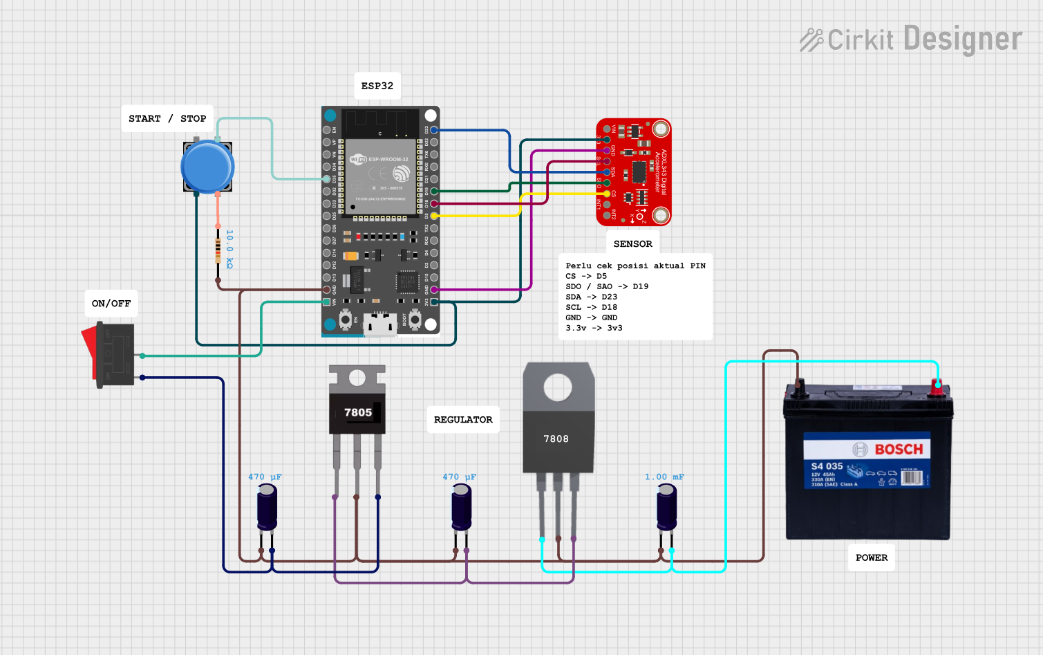
Circuit Documentation
Summary
This circuit involves an ESP32 Devkit V1 microcontroller interfaced with an Adafruit ADXL343 accelerometer, a pushbutton, a rocker switch, resistors, capacitors, and a 12V 200Ah battery. The ESP32 is programmed to read data from the accelerometer and print it to the serial monitor. The circuit also includes voltage regulation using 7805 and 7808 voltage regulators.
Component List
ESP32 Devkit V1
- Description: Microcontroller with Wi-Fi and Bluetooth capabilities.
- Pins: 3V3, GND, D15, D2, D4, RX2, TX2, D5, D18, D19, D21, RX0, TX0, D22, D23, EN, VP, VN, D34, D35, D32, D33, D25, D26, D27, D14, D12, D13, VIN
Adafruit ADXL343
- Description: 3-axis accelerometer.
- Pins: VIN, 3.3V, GND, SCL, SDA/SDIO, SDO, CS, INT1, INT2
Resistor
- Description: 10k Ohm resistor.
- Pins: pin1, pin2
- Properties: Resistance: 10k Ohms
Pushbutton
- Description: Momentary pushbutton switch.
- Pins: Pin 2, Pin 1, Pin 3, Pin 4
Rocker Switch
- Description: On/Off rocker switch.
- Pins: 1, 2
12V 200Ah Battery
- Description: Power source.
- Pins: GND, 12V
Electrolytic Capacitor
- Description: Capacitor with 0.00047 Farads capacitance.
- Pins: -, +
- Properties: Capacitance: 0.00047 Farads
Electrolytic Capacitor
- Description: Capacitor with 0.001 Farads capacitance.
- Pins: -, +
- Properties: Capacitance: 0.001 Farads
7805
- Description: 5V voltage regulator.
- Pins: Vin, Gnd, Vout
7808
- Description: 8V voltage regulator.
- Pins: INPUT, GND, OUTPUT
Wiring Details
ESP32 Devkit V1
- 3V3: Connected to Pushbutton Pin 2 and Adafruit ADXL343 3.3V
- GND: Connected to Adafruit ADXL343 GND, Resistor pin2, 7805 Gnd, Electrolytic Capacitor (-), 7808 GND, Electrolytic Capacitor (-), 12V 200Ah Battery GND
- D5: Connected to Adafruit ADXL343 CS
- D18: Connected to Adafruit ADXL343 SCL
- D19: Connected to Adafruit ADXL343 SDO
- D23: Connected to Adafruit ADXL343 SDA/SDIO
- D35: Connected to Pushbutton Pin 3
- VIN: Connected to Rocker Switch pin 2
Adafruit ADXL343
- 3.3V: Connected to ESP32 Devkit V1 3V3 and Pushbutton Pin 2
- GND: Connected to ESP32 Devkit V1 GND
- CS: Connected to ESP32 Devkit V1 D5
- SCL: Connected to ESP32 Devkit V1 D18
- SDO: Connected to ESP32 Devkit V1 D19
- SDA/SDIO: Connected to ESP32 Devkit V1 D23
Pushbutton
- Pin 2: Connected to ESP32 Devkit V1 3V3 and Adafruit ADXL343 3.3V
- Pin 3: Connected to ESP32 Devkit V1 D35
- Pin 4: Connected to Resistor pin1
Resistor
- pin1: Connected to Pushbutton Pin 4
- pin2: Connected to 7805 Gnd, Electrolytic Capacitor (-), 7808 GND, Electrolytic Capacitor (-), 12V 200Ah Battery GND, ESP32 Devkit V1 GND
Rocker Switch
- 1: Connected to 7805 Vout and Electrolytic Capacitor (+)
- 2: Connected to ESP32 Devkit V1 VIN
12V 200Ah Battery
- GND: Connected to Resistor pin2, 7805 Gnd, Electrolytic Capacitor (-), 7808 GND, Electrolytic Capacitor (-), ESP32 Devkit V1 GND
- 12V: Connected to 7808 INPUT and Electrolytic Capacitor (+)
Electrolytic Capacitor (0.00047 Farads)
- -: Connected to Resistor pin2, 7805 Gnd, 7808 GND, 12V 200Ah Battery GND, ESP32 Devkit V1 GND
- +: Connected to 7805 Vin and 7808 OUTPUT
Electrolytic Capacitor (0.001 Farads)
- -: Connected to Resistor pin2, 7805 Gnd, 7808 GND, 12V 200Ah Battery GND, ESP32 Devkit V1 GND
- +: Connected to 7808 INPUT and 12V 200Ah Battery 12V
7805
- Vin: Connected to Electrolytic Capacitor (+) and 7808 OUTPUT
- Gnd: Connected to Resistor pin2, Electrolytic Capacitor (-), 7808 GND, 12V 200Ah Battery GND, ESP32 Devkit V1 GND
- Vout: Connected to Rocker Switch pin 1 and Electrolytic Capacitor (+)
7808
- INPUT: Connected to Electrolytic Capacitor (+) and 12V 200Ah Battery 12V
- GND: Connected to Resistor pin2, 7805 Gnd, Electrolytic Capacitor (-), 12V 200Ah Battery GND, ESP32 Devkit V1 GND
- OUTPUT: Connected to 7805 Vin and Electrolytic Capacitor (+)
Code Documentation
sketch.ino
#include "SparkFun_LIS331.h"
#include <SPI.h>

LIS331 xl;

static long timer = 0;
int16_t x, y, z;

void setup()
{
  // put your setup code here, to run once:

  // Prepare SPI communication
  pinMode(5, OUTPUT);     // CS for SPI
  digitalWrite(5, HIGH);  // Make CS high
  pinMode(23, OUTPUT);    // MOSI for SPI
  pinMode(19, INPUT);     // MISO for SPI
  pinMode(18, OUTPUT);    // SCK for SPI
  SPI.begin();

  xl.setSPICSPin(5);         // This MUST be called BEFORE .begin() so
                             //.begin() can communicate with the chip

  xl.begin(LIS331::USE_SPI); // Selects the bus to be used and sets
                             //  the power up bit on the accelerometer.
                             //  Also zeroes out all accelerometer
                             //  registers that are user writable.

  Serial.begin(115200);
}

void loop(){
  if (millis() - timer > 1000){
    timer = millis();
    xl.readAxes(x, y, z);  // The readAxes() function transfers the
                           //  current axis readings into the three
                           //  parameter variables passed to it.

    Serial.println("X, Y, Z:");
    Serial.println(x);
    Serial.println(y);
    Serial.println(z);
    Serial.println(" ");

    Serial.println("G-RATING:");
    Serial.println(xl.convertToG(100,x)); // The convertToG() function
    Serial.println(xl.convertToG(100,y)); // accepts as parameters the
    Serial.println(xl.convertToG(100,z)); // raw value and the current
    Serial.println(" ");                  // maximum g-rating.
  }
}
This code initializes the SPI communication and sets up the LIS331 accelerometer. It reads the accelerometer data every second and prints the raw values and G-ratings to the serial monitor.