
Battery-Powered IR Sensor and Relay Controlled Buzzer and Motor Driver System
View and Edit Project In Cirkit Designer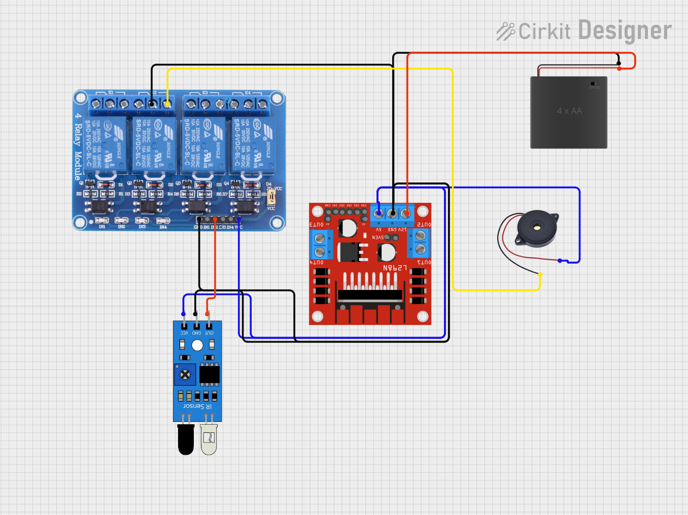
Circuit Documentation
Summary
This circuit consists of an IR sensor, a 4-channel relay module, a buzzer, an L298N DC motor driver, and a 6xAA battery pack. The IR sensor detects an object and triggers the relay, which in turn activates the buzzer. The L298N motor driver is powered by the battery pack and can control DC motors.
Component List
IR Sensor
- Description: Infrared sensor used to detect objects.
- Pins: out, gnd, vcc
Relay 4 Channel 5V
- Description: A relay module with 4 channels, used to control high voltage devices.
- Pins: GND, IN1, IN2, IN3, IN4, VCC, COM1, COM2, COM3, COM4, NO1, NO2, NO3, NO4, NC1, NC2, NC3, NC4
Buzzer
- Description: A simple buzzer used to produce sound.
- Pins: GND, IN
L298N DC Motor Driver
- Description: A motor driver module used to control DC motors.
- Pins: OUT1, OUT2, 12V, GND, 5V, OUT3, OUT4, 5V-ENA-JMP-I, 5V-ENA-JMP-O, +5V-J1, +5V-J2, ENA, IN1, IN2, IN3, IN4, ENB
6xAA Battery Pack
- Description: A battery pack holding 6 AA batteries, providing power to the circuit.
- Pins: POS, NEG
Wiring Details
IR Sensor
- out is connected to IN2 of the Relay 4 Channel 5V.
- gnd is connected to GND of the Relay 4 Channel 5V, COM2 of the Relay 4 Channel 5V, GND of the L298N DC Motor Driver, and NEG of the 6xAA Battery Pack.
- vcc is connected to VCC of the Relay 4 Channel 5V, 5V of the L298N DC Motor Driver, and IN of the Buzzer.
Relay 4 Channel 5V
- IN2 is connected to out of the IR Sensor.
- GND is connected to gnd of the IR Sensor, COM2 of the Relay 4 Channel 5V, GND of the L298N DC Motor Driver, and NEG of the 6xAA Battery Pack.
- VCC is connected to vcc of the IR Sensor, 5V of the L298N DC Motor Driver, and IN of the Buzzer.
- NO2 is connected to GND of the Buzzer.
Buzzer
- GND is connected to NO2 of the Relay 4 Channel 5V.
- IN is connected to vcc of the IR Sensor, VCC of the Relay 4 Channel 5V, and 5V of the L298N DC Motor Driver.
L298N DC Motor Driver
- GND is connected to gnd of the IR Sensor, GND of the Relay 4 Channel 5V, COM2 of the Relay 4 Channel 5V, and NEG of the 6xAA Battery Pack.
- 5V is connected to vcc of the IR Sensor, VCC of the Relay 4 Channel 5V, and IN of the Buzzer.
- 12V is connected to POS of the 6xAA Battery Pack.
6xAA Battery Pack
- POS is connected to 12V of the L298N DC Motor Driver.
- NEG is connected to gnd of the IR Sensor, GND of the Relay 4 Channel 5V, COM2 of the Relay 4 Channel 5V, and GND of the L298N DC Motor Driver.
Code
There is no code provided for this circuit.